


61
FX3G/FX3U/FX3UC Series Programmable Controllers
Programming Manual - Basic & Applied Instruction Edition
2 Overview (Sequence Program)
2.7 Types and Setting of Parameters
1
Introduction
2
Overview
3
Instruction
List
4
Devices
in Detail
5
Specified the
Device &
Constant
6
Before
Programming
7
Basic
Instruction
8
FNC00-FNC09
Program Flow
9
FNC10-FNC19
Move & Compare
10
FNC20-FNC29
Arith. & Logic
Operation
*1. The setting range is from 10 to 100,000 Hz in FX3G/FX3U/FX3UC PLCs.
The setting range is from 10 to 200,000 Hz in FX
3U PLCs when the pulse output destination is the FX3U-
2HSY-ADP.
*2. The creep speed should satisfy the relationship "Bias speed ≤ Creep speed ≤ Maximum speed."
*3. An interrupt input set here cannot be used jointly with a high speed counter, input interrupt, pulse catch input,
input in SPD (FNC 67) instruction, or interrupt input in DVIT (FNC151) instruction.
*4. This area can be set only in FX
3U/FX3UC PLCs.
*5. Y002 is not available in 14-point and 24-point type FX
3G PLC.
*6. Note that this item can only be set if two FX
3U-2HSY-ADP adapters are connected to the FX3U PLC.
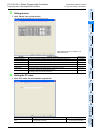
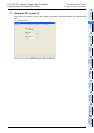
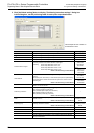
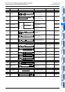
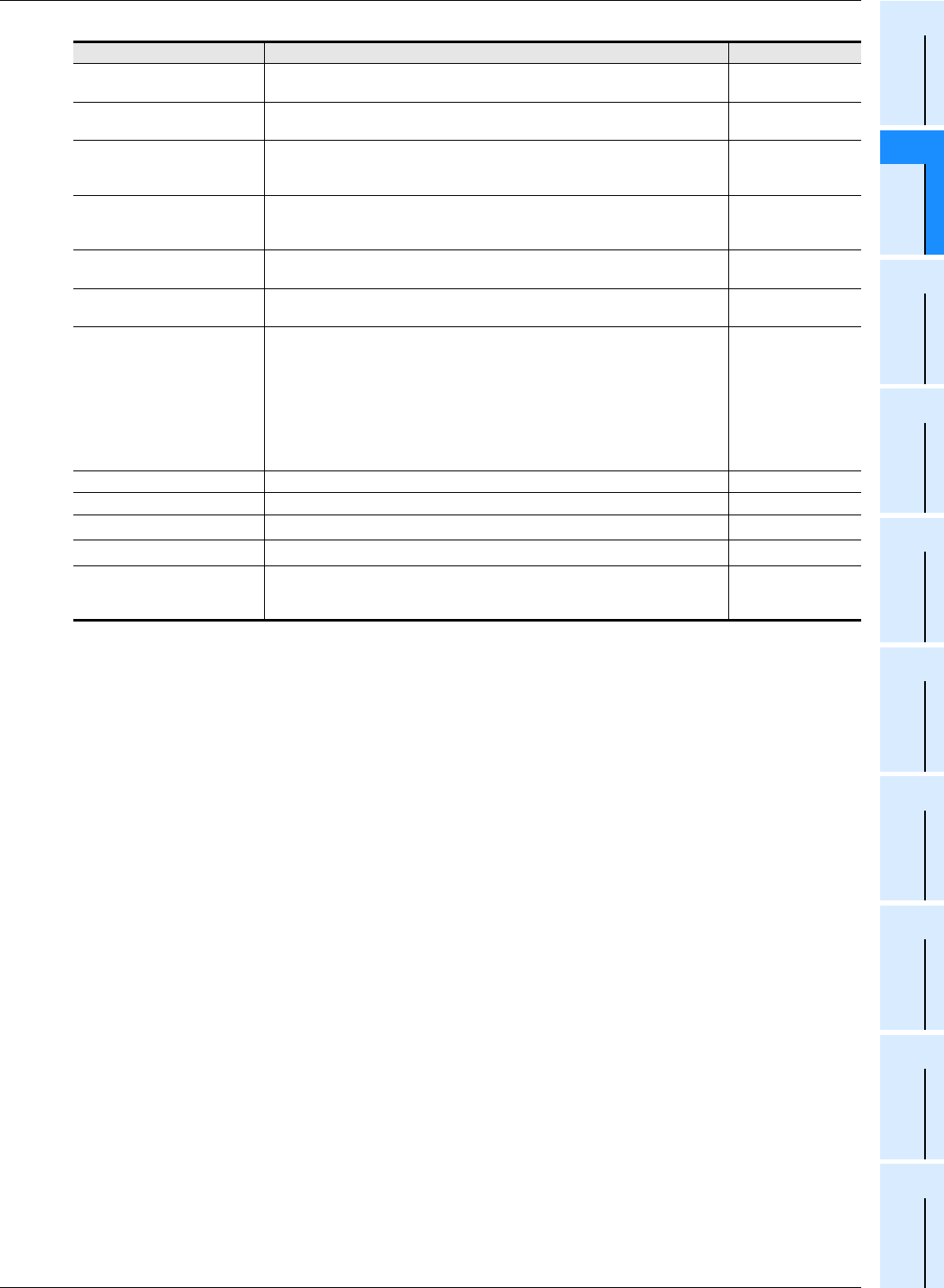
Set item Contents of setting Set range
Bias speed [Hz]
Set the bias speed for each output number of pulse.
Initial value: 0
1/10 or less of the
maximum speed
Max. speed [Hz]
Set the maximum speed for each output number of pulse.
Initial value: 100,000
*1
Creep speed [Hz]
Set the creep speed in DSZR (FNC150) instruction for each output number of
pulse.
Initial value: 1000
10 to 32767
*2
Zero return speed [Hz]
Set the zero point return speed in DSZR (FNC150) instruction for each output
number of pulse.
Initial value: 50000
*1
Acceleration time [ms]
Set the acceleration time for each output number of pulse.
Initial value: 100
50 to 5000
Deceleration time [ms]
Set the deceleration time for each output number of pulse.
Initial value: 100
50 to 5000
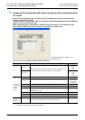
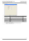
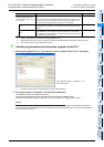
Interruption input of DVIT
instruction
*4
Set the interrupt input
*3
for DVIT (FNC151) instruction for each output number of
pulse. Specify a user interrupt command device (M) for a pulse output
destination device not used in DVIT instruction.
Initial setting: Setting range:
Pulse output destination Y000: X000 X000 to X007, M8460
Pulse output destination Y001: X001 X000 to X007, M8461
Pulse output destination Y002: X002 X000 to X007, M8462
Pulse output destination Y003
*6
: X003 X000 to X007, M8463
As shown on the left
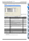
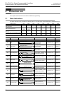
Y0 They are set items for the pulse output destination Y000. –
Y1 They are set items for the pulse output destination Y001. –
Y2
*5
They are set items for the pulse output destination Y002. –
Y3
*6
They are set items for the pulse output destination Y003. –
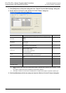
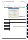
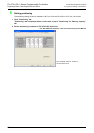
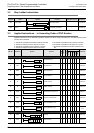
Individual setting
This button displays "Positioning instruction settings" dialog box for setting the
table used in TBL (FNC152) instruction.
→For the setting procedure, refer to the next step.
–