


254
FX3G/FX3U/FX3UC Series Programmable Controllers
Programming Manual - Basic & Applied Instruction Edition
9 Move and Compare – FNC 10 to FNC 19
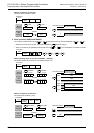
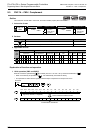
9.6 FNC 15 – BMOV / Block Move
9.6.1 Function of transfer between file registers and data registers
BMOV (FNC 15) instruction has a special function for file registers (D1000 and later).
→ For details on file registers, refer to Section 4.8.
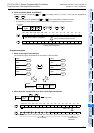
1. What are file registers
By parameter setting, D1000 to D7999 can be handled as file registers, and written to and read from the program
memory area.
1) Outline of setting
File registers (D1000 to D7999) do not exist in the initial status. They are valid only when some number of file
registers are secured by parameter setting in a programming tool.
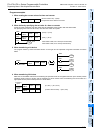
2) Number of file registers
In parameter setting, set 500 file registers as 1 block.
1 to 14 blocks (each of which has 500 file registers) can be set.
1 block occupies 500 steps in the program memory area.
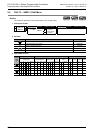
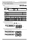
3) Difference between BMOV (FNC 15) instruction and other instructions
The table below shows the difference between BMOV (FNC 15) instruction and other instructions with regard to
file registers (D1000 and later).
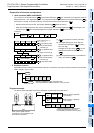
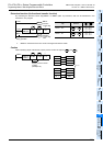
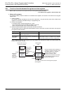
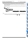
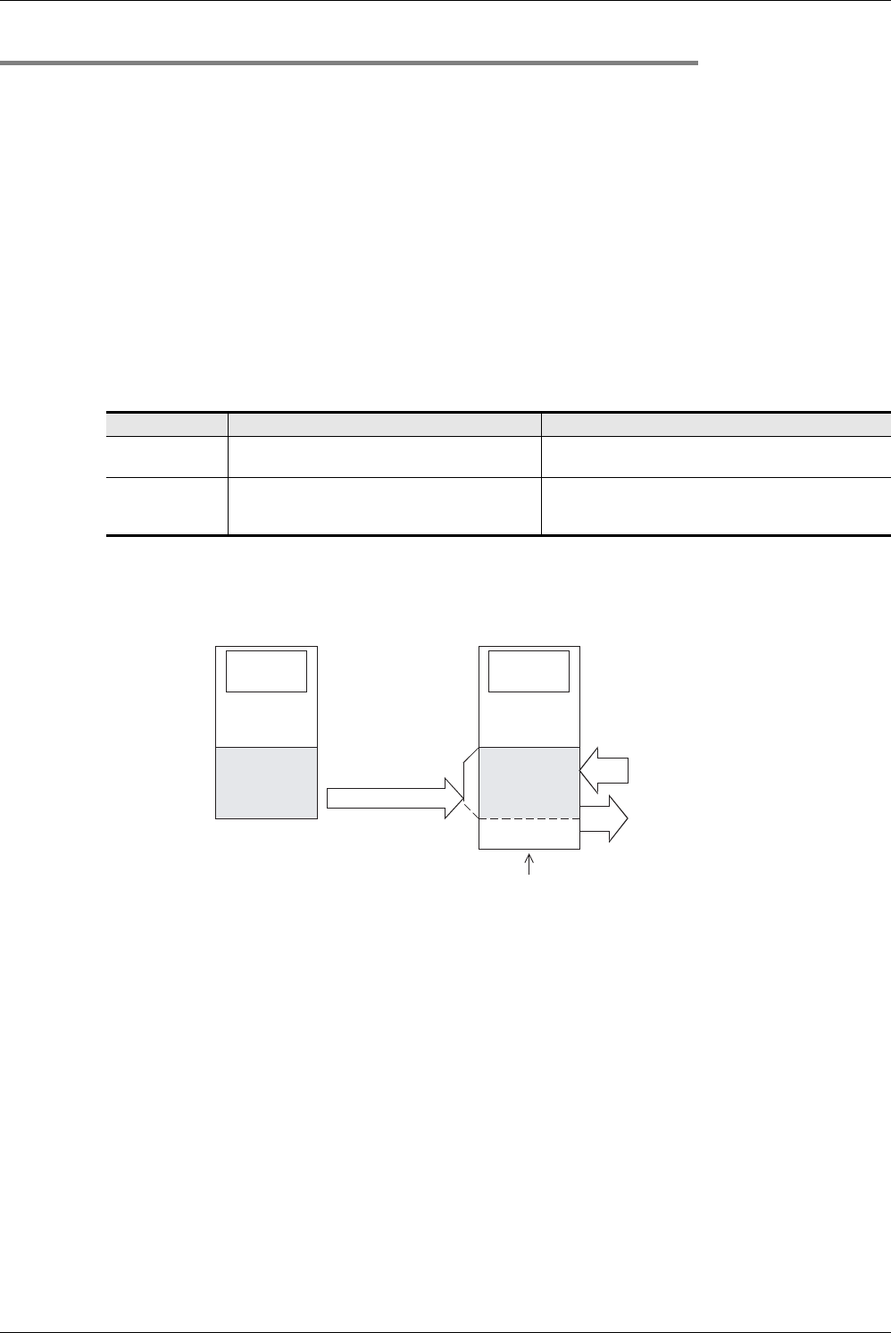
When restoring the power, data registers set as file registers are automatically copied from the file register area
[A] to the data register area [B].
Instruction Contents of transfer Remarks
BMOV instruction
Can read from and write to the file register area [A]
inside the program memory.
−
Other applied
instructions
Can read from and write to the data register area
[B] inside the program memory in the same way as
general data registers.
Because the data register area [B] is provided inside the
system RAM in PLCs, its contents can be arbitrarily
changed without regard to the memory cassette format
Data register
[B]
Inside system
RAM
Inside built-in memory
or memory cassette
Program
memory
Program/
comment
File register
[A]
D1000
500 points ×
14 blocks
maximum
(7000 points
maximum)
When power
is turned ON
When PLC
mode is
changed from
STOP to
RUN
Data
memory
Data register
Data register
D7999
D1000
D 0
Read
Write
The remaining area can be used as general purpose
data registers.
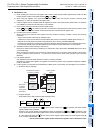
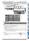
Devices D1000 and later specified as
operands in applied instructions othe
r
than BMOV (FNC 15) , indirectly
specified values for timers or
counters or devices in RST
instruction are read from and written
to the area [B] in the same way as
general data registers.