


743
FX3G/
FX
3U
/FX
3UC
Series Programmable Controllers
Programming Manual - Basic & Applied Instruction Edition
34 FX3U-CF-ADP Applied Instructions – FNC300 to FNC305
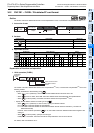
34.3 FNC 302 – FLWR / Data write
31
FNC275-FNC279
Data
Transfer 3
32
FNC280-FNC289
High Speed
Processing 2
33
FNC290-FNC299
Extension File
Register
34
FNC300-FNC305
FX
3U
-CF-ADP
35
SFC•STL
Programming
36
Interrupt
Function
37
Special Device
38
Error Code
A
Version Up
Information
B
Execution Times
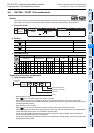
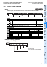
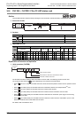
34.3.1 Detailed explanation of setting data
Details of the setting data in the FLWR instruction are as shown below.
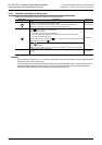
Cautions
• The FLWR instruction is completed abnormally if a CompactFlash
TM
card is not mounted.
• The user should pay close attention to the number of times data is written when the writing destination is set to the
CompactFlash
TM
card because data is written every time the FLWR instruction is executed.
For example, if data is written to the CompactFlash
TM
card every one minute, data is written 100,000 times in
approximately 2 months.
• Even if the writing destination is set to the buffer inside the CF-ADP, data is written to the CompactFlash
TM
card in
the case of overwriting.
• The FLWR instruction writes data to the CompactFlash
TM
card after the internal buffer inside the CF-ADP becomes
full when the writing destination is set to the buffer. Data stored in the internal buffer inside the CF-ADP is erased
when a (instantaneous or long) power interruption occurs.
• When the data type is a data name (K8), the user can specify only the head line position before writing other data.
Index and DATE TIME are added automatically.
• The FLWR instruction may require several scans to acquire data. Take proper measures such as saving acquired
data in another device if data consistency is required.
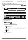
• It is necessary to set the device number in multiples of 16 when a bit device is specified in
and the data type
is set to anything other than bit type. When a word device is specified in and the data type is set to bit, the
FLWR instruction acquires data to be written from the least significant bit of the specified device.
• When is "K7" or "K8", 00H, which indicates the end of the string, must be added to the end of the character
string.
• It is not permitted to use an RS (FNC 80)/RS2 (FNC 87)/IVCK (FNC270)/IVDR (FNC271)/IVRD (FNC272)/IVWR
(FNC273)/IVBWR (FNC274) instruction and an FLCRT (FNC300)/FLDEL (FNC301)/FLWR (FNC302)/FLRD
(FNC303)/FLCMD (FNC304)/FLSTRD (FNC305) instruction for the same port.
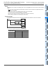
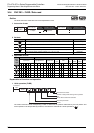
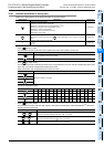
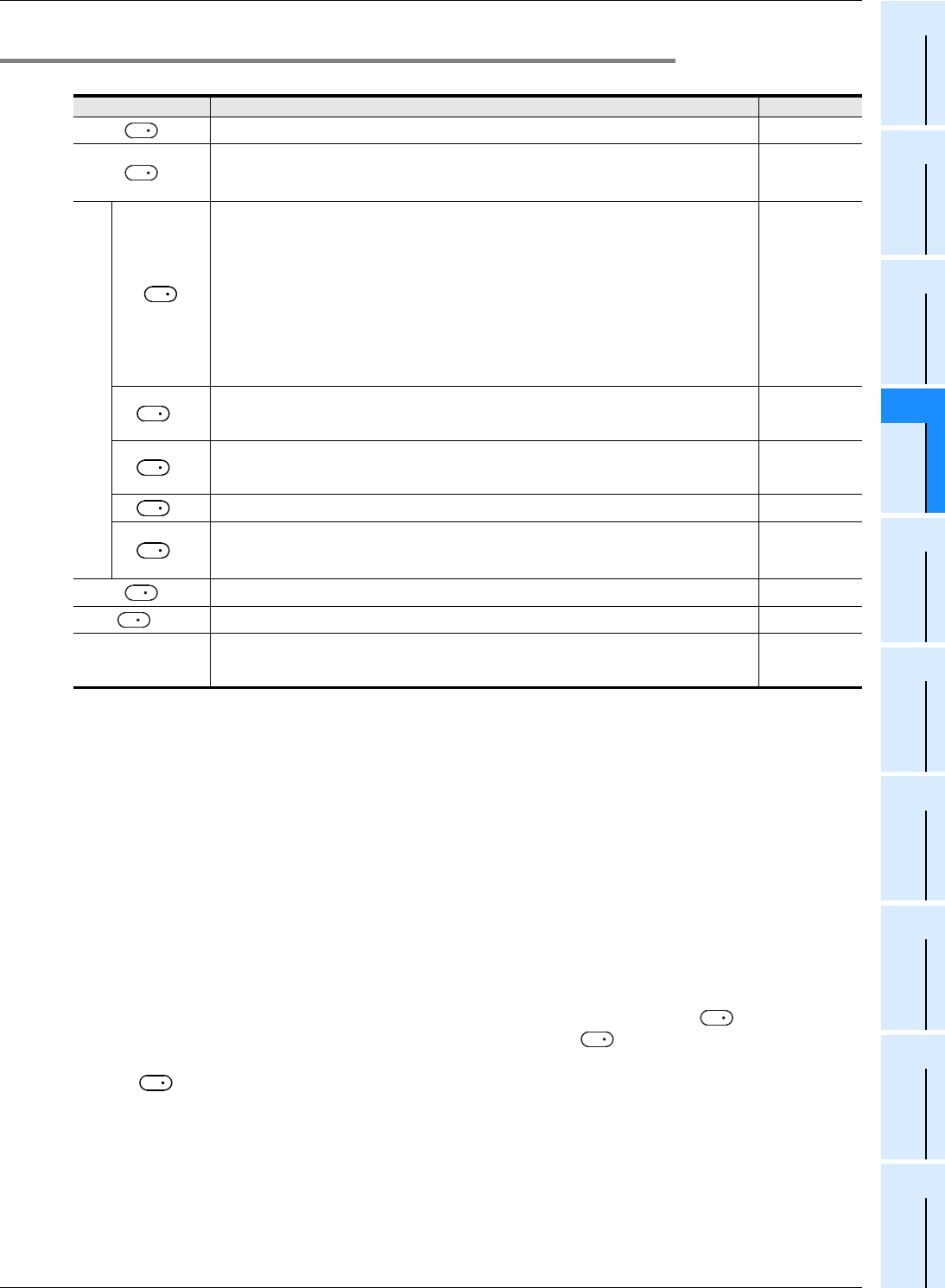
Setting items Description Data Type
File ID : K0 to K63 16-bit binary
Head of devices which store data to be written.
Specify the head of devices which store the data to be written to the CompactFlash
TM
card.
-
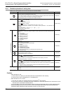
Data write parameter
Specify the data writing type
K0 : Mixed type
K1 : Bit type
K2 : Decimal type (16-bit)
K3 : Decimal type (32-bit)
K4 : Hexadecimal type (16-bit)
K5 : Hexadecimal type (32-bit)
K6 : Real numbers(Floating point data) Exponent expression type (32-bit)
K7 : Character string (512 half-width/full-width characters maximum)
K8 : Data name : Character string consisting of up to 32 half-width/full-width
characters. Index, DATE TIME are added automatically.
16-bit binary
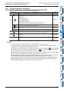
+1
Specify the line position of the writing destination, or specify additional writing.
Line position of the writing destination : K1 to specified maximum number of lines
Additional writing : K-1
16-bit binary
+2
Specify the data column position in the writing destination.
Column position : K1 to K254
Additional writing : K-1
16-bit binary
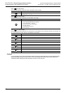
+3
Number of written data points : K1 to K254 16-bit binary
+4
Writing destination
K0 : CompactFlash
TM
card
K1 : Buffer inside the CF-ADP
16-bit binary
Line position after writing : K1 to specified maximum number of lines 16-bit binary
+1
Column position after writing : K1 to K254 16-bit binary
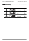
n
Channel number used by the CF-ADP
K1 : ch1
K2 : ch2
16-bit binary
S
1
S
2
S
3
S
3
S
3
S
3
S
3
D
D
S
2
S
2
S
3