


853
FX3G/FX3U/FX3UC Series Programmable Controllers
Programming Manual - Basic & Applied Instruction Edition
37 Operation of Special Devices (M8000 -, D8000 -)
37.2 Supplement of Special Devices (M8000 - and D8000 -)
31
FNC275-FNC279
Data
Transfer 3
32
FNC280-FNC289
High Speed
Processing 2
33
FNC290-FNC299
Extension File
Register
34
FNC300-FNC305
FX
3U
-CF-ADP
35
SFC•STL
Programming
36
Interrupt
Function
37
Special Device
38
Error Code
A
Version Up
Information
B
Execution Times
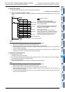
37.2.2 Watchdog timer [D8000]
The watchdog timer monitors the operation (scan) time of the PLC. When the operation is not completed within the
specified time, ERROR (ERR) LED light turns on and all outputs are turned OFF.
When the power is initially turned ON, "200 ms" is transferred from the system to D8000 as the default value. For
executing a program beyond 200 ms, the contents of D8000 must be changed by the user program.
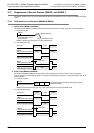
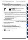
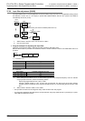
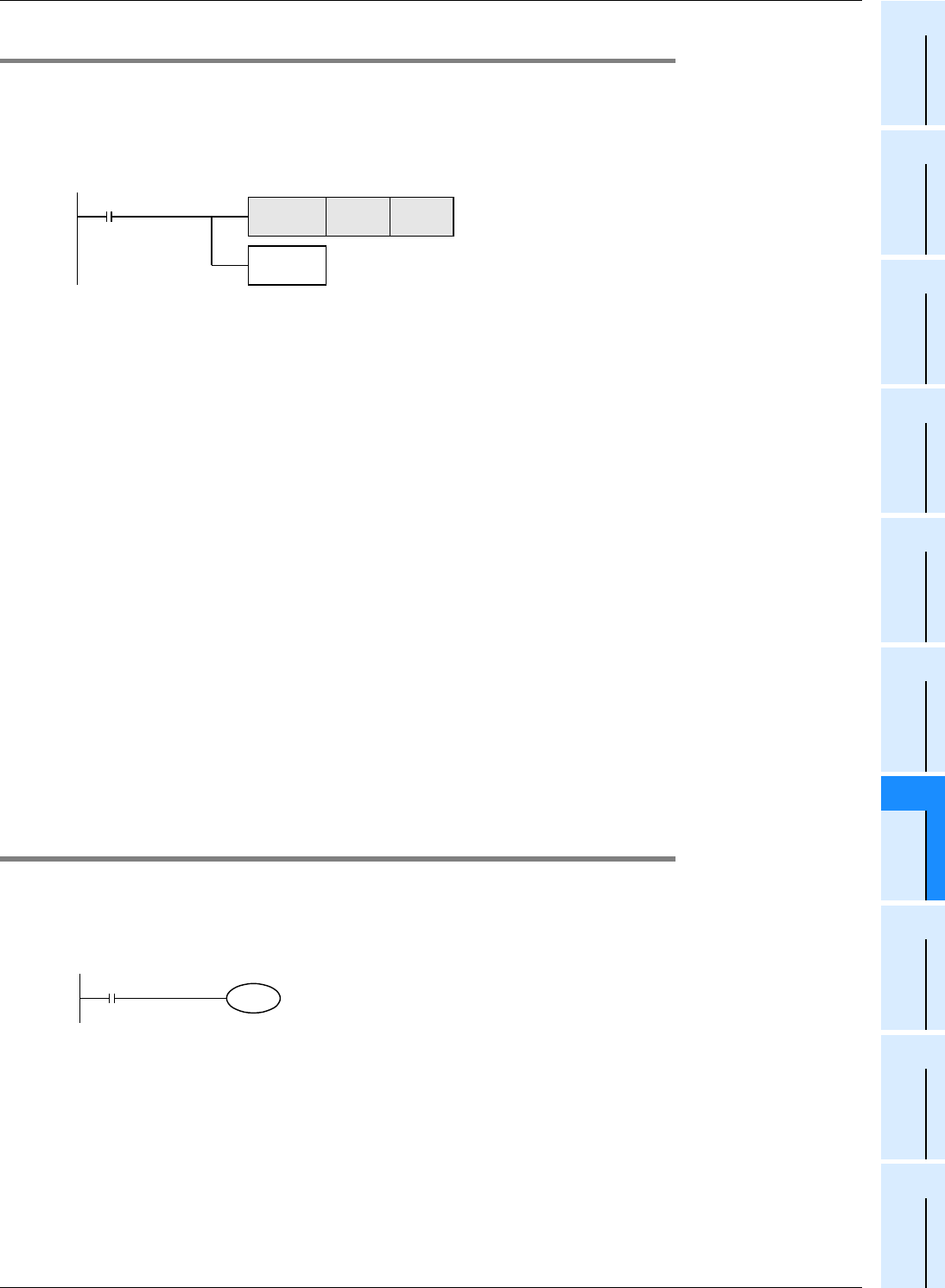
1. Example program
2. When a watchdog timer error occurs
A watchdog timer error may occur in the following cases. Add the above program to somewhere near the first step or
adjust the number of execution FROM/TO instructions at the same scan.
1) When using many special function units/blocks
When many special function units/blocks (such as positioning, cam switches, link and analog) are used, buffer
memory initial setting time becomes long at turning on the PLC, thus extending the operation time and allowing
the possibility for a watchdog timer error to occur.
2) When executing many FROM/TO instructions at the same time
When many FROM/TO instructions are executed or when many buffer memories are transferred, it extends the
scan time, and a watchdog timer error may occur.
3) When using many high speed counters (software counters)
When many high speed counters are programmed and high frequency is counted at the same time, it extends the
scan time, and a watchdog timer error may occur.
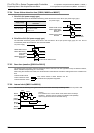
3. How to reset the watchdog timer
The watchdog timer can be reset in the middle of a sequence program using WDT (FNC 07) instruction.
It is recommended to reset the watchdog timer by WDT (FNC 07) instruction when the scan time of a particular
sequence program is extended or when many special function units/blocks are connected.
→ For WDT (FNC 07) instruction, refer to Section 8.8.
4. Cautions on changing the watchdog timer
The watchdog timer time can be set to a maximum of 32767 ms. However, CPU error detection is delayed when the
watchdog timer time is extended.
It is recommended to use the default value (200 ms) when no problems are to be expected in operation.
37.2.3 Battery voltage low detection [M8005 and M8006]
This special device detects low voltage in the lithium battery for memory backup.
In FX
3U/FX3UC PLCs, the BATT (BAT) LED turns ON when the PLC detects low battery voltage.
In FX
3G PLCs, the ALM LED indicator turns ON when the PLC detects low battery voltage if the optional battery is
installed and the battery mode is selected by the parameter setting.
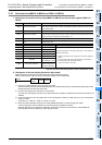
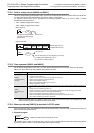
Use the following program to notify low battery voltage to the outside.
M8002
Initial pulse
FNC 12
MOV
K300 D8000
FNC 07
WDT
Setting value of watchdog timer is set to "300 ms."0
The watchdog timer
When WDT (FNC 07) instruction is not programmed, the
value stored in D8000 is not valid until END processing.
M8005
Battery
voltage low
"Battery voltage low"
Y001
M8006 latches the battery voltage low.
0