


99
FX3G/FX3U/FX3UC Series Programmable Controllers
Programming Manual - Basic & Applied Instruction Edition
4 Devices in Detail
4.6 Counter [C]
1
Introduction
2
Overview
3
Instruction
List
4
Devices
in Detail
5
Specified the
Device &
Constant
6
Before
Programming
7
Basic
Instruction
8
FNC00-FNC09
Program Flow
9
FNC10-FNC19
Move & Compare
10
FNC20-FNC29
Arith. & Logic
Operation
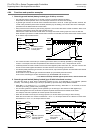
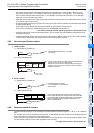
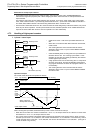
• The current value increases or decreases regardless of the operation of the output contact. When a counter
executes up-counting from "+2,147,483,647", the counter value becomes "−2,147,483,648". In the same way,
when a counter executes down-counting from "−2,147,483,648", the counter value becomes "+2,147,483,647".
(This type of counter is called ring counter.)
• When the reset input X013 turns ON and then RST instruction is executed, the current value of the counter is reset
to "0" and the output contact returns.
• For latched (battery backed) type counters, the current value, output contact operation and reset status are backed
up against power failure.
In FX
3U/FX3UC PLCs, latched type counters are backed up by the battery built into the PLC.
In FX
3G PLCs, latched type counters are backed up by the EEPROM built into the PLC.
→ For details on backup methods against power failure, refer to Section 2.6.
• A 32-bit counter can be used as a 32-bit data register. 32-bit counters cannot be handled as target devices in 16-
bit applied instructions.
• If data beyond the set value is written to the current value register by DMOV instruction, etc., the counter continues
counting and the contact does not change when the next counting input is received.
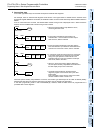
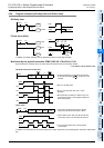
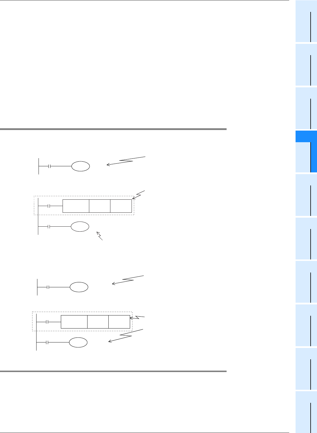
4.6.5 Set value specification method
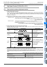
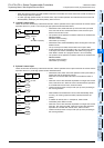
1. 16-bit counter
1) Specification by constant (K)
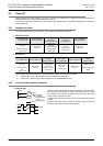
2) Indirect specification (D)
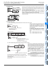
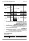
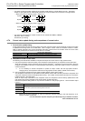
2. 32-bit counter
1) Specification by constant (K)
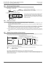
2) Indirect specification (D)
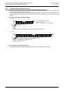
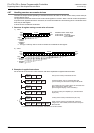
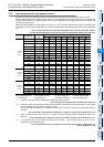
4.6.6 Response speed of counters
Counters execute counting by cyclic operating for contact operations of internal signals X, Y, M, S, C, etc. inside the
PLC.
For example, when X011 is specified as counting input, its ON duration and OFF duration should be longer than the
cycle time of the PLC (which is tens of Hz or less usually).
On the other hand, high speed counters described later execute counting as an interrupt processing for specific input,
and can execute counting at 5 k to 6 kHz regardless of the cycle time.
→ For high speed counters, refer to Section 4.7.
X003
C 0
K100
Constant (decimal constant): 1 to 32767
100 counts
X001
FNC 12
MOV
K100 D 5
X003
C 0
D 5
D5 = 100
100 counts
Counts to the indirectly specified value of the defined data
register, previously set by a digital switch.
Note that the set value of a latched (battery backed) type
register is not held correctly sometimes when the battery
voltage becomes low.
X003
C200
K43,210
Constant (decimal constant):
−
2,147,483,648 to +2,147,483,647
43210 counts
X001
FNC 12
DMOV
K43210 D5(D6)
X003
C200
D5(D6)
Pairs of data registers are used for indirect specification.
Use a 32-bit instruction for writing the set value, and make
sure that the latter of paired registers (D6 in this example)
does not overlap with other programs because it is not
shown in ladder format.