


821
FX3G/FX3U/FX3UC Series Programmable Controllers
Programming Manual - Basic & Applied Instruction Edition
37 Operation of Special Devices (M8000 -, D8000 -)
37.1 Special Device List (M8000 -, D8000 -)
31
FNC275-FNC279
Data
Transfer 3
32
FNC280-FNC289
High Speed
Processing 2
33
FNC290-FNC299
Extension File
Register
34
FNC300-FNC305
FX
3U
-CF-ADP
35
SFC•STL
Programming
36
Interrupt
Function
37
Special Device
38
Error Code
A
Version Up
Information
B
Execution Times
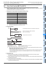
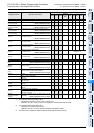
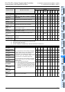
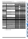
Step Ladder and Annunciator (Refer to ANS (FNC 46), ANR (FNC 47), IST (FNC 60), and Chapter 35 for details.)
M 8040
Transfer disable
While M8040 is turned ON, transfer between states is
disabled.
3 3 3 – 33333
[M]8041
*1
Transfer start
Transfer from initial state is enabled in automatic
operation mode.
3 3 3 – 33333
[M]8042
Start pulse
Pulse output is given in response to a start input.
3 3 3 – 33333
M 8043
*1
Zero return complete
Set this in the last state of zero return mode.
3 3 3 – 33333
M 8044
*1
Zero point condition
Set this when machine zero return is detected.
3 3 3 – 33333
M 8045
All output reset
disable
Disables the ’all output reset’ function when the
operation mode is changed.
3 3 3 – 33333
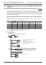
[M]8046
*2
STL state ON
ON when M8047 is ON and any state S0 to S899 or
S1000 to S4095
*3
is active.
3 3 3 M8047 3333 3
M 8047
*2
STL monitoring
enable
D8040 to D8047 are enabled when M8047 is ON.
3 3 3
D8040 to
D8047
3333 3
[M]8048
*2
Annunciator operate
ON when M8049 is ON and any annunciator S900 to
S999 is ON.
3 3 3 –––3 – 3
M 8049
*1
Annunciator enable
D8049 is enabled when M8049 is ON.
3 3 3
D8049
M8048
––3 – 3
*1. Cleared when the PLC switches from RUN to STOP.
*2. Executed at END instruction.
*3. S1000 to S4095 are available only in the FX
3G/FX3U/FX3UC Series PLC.
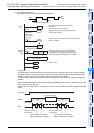
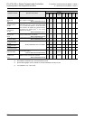
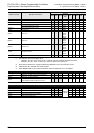
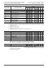
Interrupt Disable (Refer to Subsection 36.2.1.) for details.
M8050 (input interrupt)
I00
disable
*4
• If an input interrupt or timer interrupt occurs while a
special auxiliary relay for that interrupt (M8050 -
M8058) is ON, the interrupt will not operate.
For example, turning M8050 ON disables the I00
interrupt; hence, the interrupt routine is not
processed even in an allowable program area.
• If an input interrupt or timer interrupt occurs while a
special auxiliary relay for that interrupt (M8050 -
M8058) is OFF,
a) The interrupt will be accepted.
b) The interrupt routine will be processed promptly
if it is permitted by the EI (FNC 04) instruction.
However, if the DI (FNC 05) instruction disables
interrupts, the interrupt program will not be
processed until EI (FNC 04) permits the
interrupts.
3 3 3 – 33333
M8051 (input interrupt)
I10
disable
*4
3 3 3 – 33333
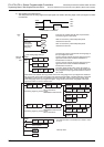
M8052 (input interrupt)
I20
disable
*4
3 3 3 – 33333
M8053 (input interrupt)
I30
disable
*4
3 3 3 – 33333
M8054 (input interrupt)
I40
disable
*4
3 3 3 – 33333
M8055 (input interrupt)
I50
disable
*4
3 3 3 – 33333
M8056
(Timer interrupt)
I6
disable
*4
3 3 3 –––3 – 3
M8057
(Timer interrupt)
I7
disable
*4
3 3 3 –––3 – 3
M8058
(Timer interrupt)
I8
disable
*4
3 3 3 –––3 – 3
M8059
Counter interrupt
disable
*4
Interrupt of I010 to I060 disabled – 3 3 –––3 – 3
*4. Cleared when the PLC switches from RUN to STOP.
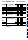
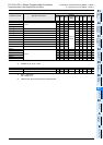
Number and name Operation and function
Applicable model
FX
3G FX3U
FX
3UC
Correspond-
ing special
device
FX
1S
FX
1N
FX
2N
FX
1NC
FX
2NC