


30
FX3G/FX3U/FX3UC Series Programmable Controllers
Programming Manual - Basic & Applied Instruction Edition
2 Overview (Sequence Program)
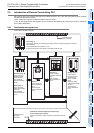
2.5 Introduction of Devices Constructing PLC
2.5.2 Device list
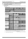
1. Input relays (X) and output relays (Y)
→ Refer to Section 4.2.
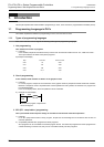
• Input relay and output relay numbers are
assigned to each main unit in octal "X000 to X007,
X010 to X017 …, Y000 to Y007, Y010 to Y017 …"
The input relay (X) numbers and output relay (Y)
numbers in extension units and extension blocks
are also sequential numbers in octal respectively
in the order of connection to the main unit.
• A digital filter is applied to the input filter of specific
input relays, and the filter value can be changed
by a program. Accordingly, for a purpose
requiring high speed receiving, assign such input
relay numbers.
(Refer to explanation of filter adjustment, input
interrupt, high speed counter, various applied
instructions, etc.)
2. Auxiliary relays (M)
→ Refer to Section 4.3.
• Relays built into the PLC are auxiliary relays, and
are used for programs. Different from I/O relays,
auxiliary relays cannot receive external inputs or
directly drive external loads.
• There are latched (battery or EEPROM backed)
type relays whose ON/OFF status is stored even if
the PLC turns OFF.
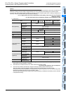
3. State relays (S)
→ Refer to Section 4.4.
• State relays are used in the step ladder or as
process numbers in the SFC expression.
• When a state relay is not used as a process
number, it can be programmed as a general
contact/coil in the same way as an auxiliary relay.
• State relays can be used as annunciators for
external fault diagnosis.
4. Timers (T)
→ Refer to Section 4.5.
• A timer adds and counts clock pulses of 1, 10 or
100 ms, and turns its output contact ON or OFF
when the counted result reaches a specified set
value.
A timer can count from 0.001 to 3276.7 seconds
depending on the clock pulse.
• The timers T192 to T199 are dedicated to
subroutines and interrupt routines.
The timers T250 to T255 are retentive type base
clock timers for 100 ms pulses. This means that
the present value is retained even after the timer
coil drive input turns OFF. And when the drive
input turns ON again, a retentive type timer will
continue its counting from where it left off.
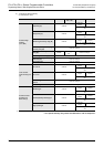
5. Counters (C)
The following types of counters are provided, and
can be used in accordance with the purpose or
application.
1) For latched (battery or EEPROM backed)
counters
→ Refer to Section 4.6.
Counters are provided for internal signals of the
PLC, and their response speed is usually tens of
Hz or less.
- 16-bit counter: Provided for up-counting,
counting range: 1 to 32767
- 32-bit counter: Provided for up-counting
and down-counting, counting range:
−2,147,483,648 to +2,147,483,647
2) For latched (battery or EEPROM backed) high
speed counters
→ Refer to Section 4.7.
High speed counters can execute counting at
several kHz regardless of operations in the PLC.
- 32-bit counter: Provided for up-counting
and down-counting, counting range:
−2,147,483,648 to +2,147,483,647 (1-
phase 1-counting, 1-phase 2-counting and
2-phase 2-counting), assigned to specific
input relays
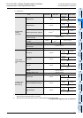
6. Data registers (D)
→ Refer to Section 4.9.
Data registers store numeric data values.
All data registers in FX PLCs are 16-bit type (whose
most significant bit is positive or negative). When two
consecutive registers are combined, they can handle
32-bit numeric value (whose most significant bit is
positive or negative).
(For the numeric value range, refer to "Counter" on
the previous page.)
In the same way as other devices, data registers are
classified into general type and latched type (battery
or EEPROM backed).
7. Extension registers (R) and extension file
registers (ER)
→ Refer to Section 4.10.
Extension registers (R) are the extended form of data
registers (D). They are protected by the battery
against power failure in FX
3U/FX3UC PLCs.
In FX
3G PLCs, general type devices can be
protected against power failure when the optional
battery is connected.
In FX
3G/FX3U/FX3UC PLCs, the contents of
extension registers (R) can be stored in extension file
registers (ER).
In FX
3U/FX3UC PLCs, extension file registers (ER)
can only be used while a memory cassette is
mounted.