594
FX3G/FX3U/FX3UC Series Programmable Controllers
Programming Manual - Basic & Applied Instruction Edition
24 Others – FNC181 to FNC189
24.4 FNC188 – CRC / Cyclic Redundancy Check
Program example
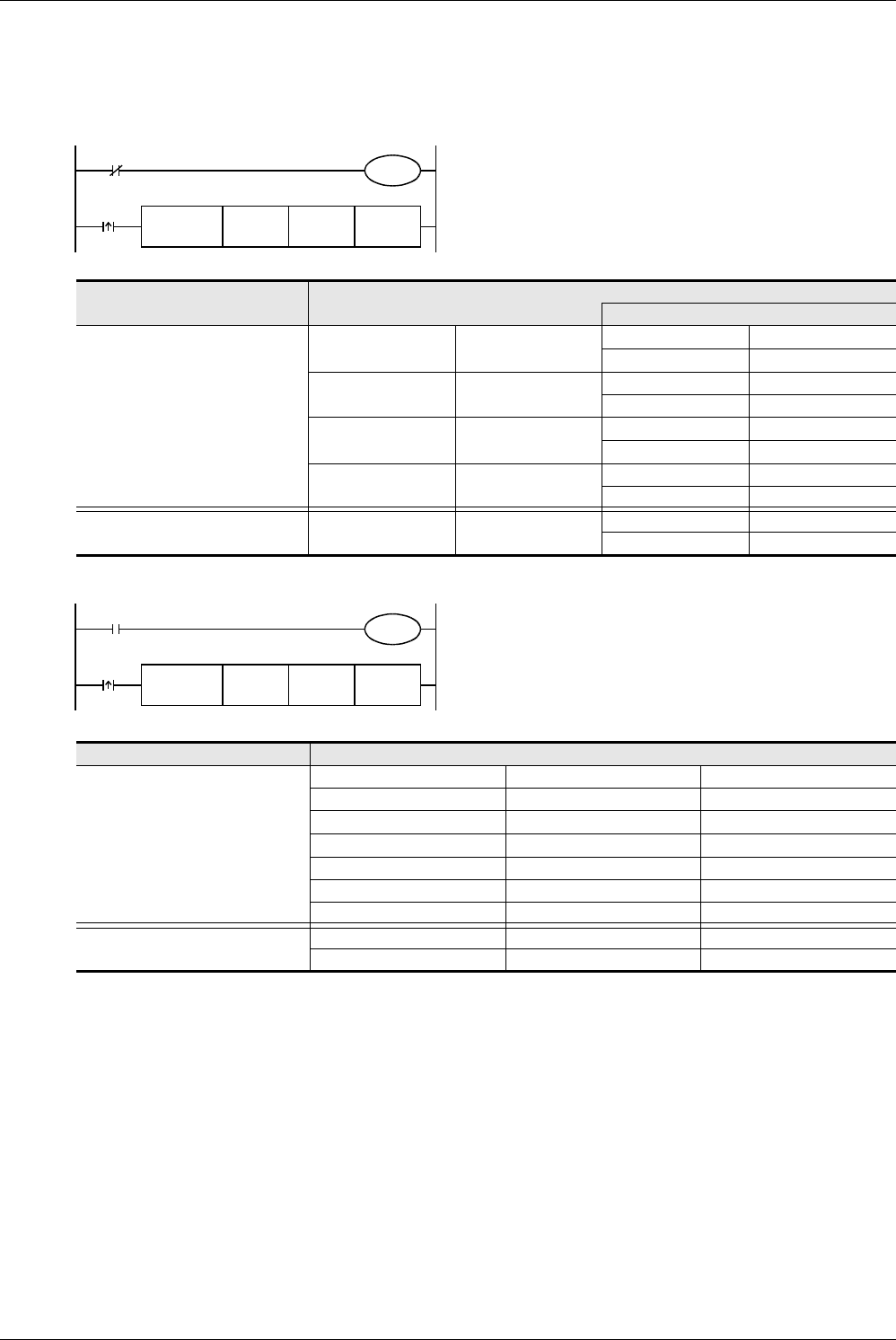
In the program example shown below, the CRC value of the ASCII code “0123456” stored in D100 to D106 is
generated and stored to D0 when M0 turns ON.
1. In the case of 16-bit mode
2. In the case of 8-bit mode
Contents of data
Target data
Device storing data for which CRC
value is generated
D100 3130H
Low-order byte 30H
High-order byte 31H
D101 3332H
Low-order byte 32H
High-order byte 33H
D102 3534H
Low-order byte 34H
High-order byte 35H
D103 3736H
Low-order byte 36H
––
Device storing generated CRC value D0 2ACFH
Low-order byte CFH
High-order byte 2AH
Contents of target data
Device storing data for which the
CRC value is generated
D100 Low-order byte 30H
D101 Low-order byte 31H
D102 Low-order byte 32H
D103 Low-order byte 33H
D104 Low-order byte 34H
D105 Low-order byte 35H
D106 Low-order byte 36H
Device storing the generated CRC
value
D0 Low-order byte CFH
D1 Low-order byte 2AH
M0
FNC188
CRC
D100 D0 K7
M8161
M8000
16-bit conversion mode
FNC188
CRC
M8161
M8000
D100 D0 K7
M0
8-bit conversion mode


