


86
FX3G/FX3U/FX3UC Series Programmable Controllers
Programming Manual - Basic & Applied Instruction Edition
4 Devices in Detail
4.2 I/O Relays [X, Y]
4.2.3 Operation timing of input relays
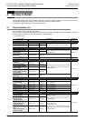
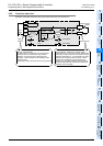
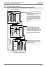
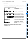
The PLC executes sequence control by repeatedly executing the following processing procedure. In this batch I/O
method, not only are there driving times of input filters and output devices but also response delays caused by
operation cycles. (Refer to Section 6.3.)
Input processing
Input terminal
Input
Image
Memory
1) Read-in
X000
X001
X002
Program processing
Device
Image
Memory
Output processing
Output terminal
Output
Latch
Memory
6) Output
Y000
Y001
Y002
X000
M 0
4) Read-
out
Y000
Auxiliary
relay
2) Read-out
Repeated operation
[The time required for a cyclic
operation is called operation cycle
(scan time).]
Y000
Input processing
Before executing a program, the PLC reads the ON/
OFF status of all input terminals inside the PLC into
the input image memory.
Even if inputs change while the program is
executed, the contents of the input image memory
remain unchanged, but the changes in inputs are
read during the input processing in the next cycle.
Even if an input contact changes from ON to OFF or
from OFF to ON, its ON/OFF status is judged after
the response delay (approximately 10 ms) caused
by the input filter.
(When the input filter is a digital type input terminal ,
its value can be overwritten by a sequence
program.)
Program processing
The PLC reads the ON/OFF status of each device
from the input image memory and other device
image memories according to the contents of
instructions in the program memory, executes
operations in sequence from step 0, and then writes
the operation result to the image memory.
Accordingly, the contents of the image memory for
each device change as the program is executed.
The operation of a contact inside an output relay is
determined by the contents of the output image
memory.
Output processing
When execution of all instructions is finished, the
ON/OFF status of the image memory of outputs (Y)
is transferred to the output latch memory. This is
the actual output of the PLC.
External output contacts inside the PLC operate
after the response delay time of the output devices.
The above method is called the batch I/O method (or refresh method).
1) 2) 3) .... 6) indicate the processing order.
3) Write
5) Write