


549
FX3G/FX3U/FX3UC Series Programmable Controllers
Programming Manual - Basic & Applied Instruction Edition
20 Positioning Control – FNC150 to FNC159
20.2 FNC151 – DVIT / Interrupt Positioning
11
FNC30-FNC39
Rotation and
Shift
12
FNC40-FNC49
Data Operation
13
FNC50-FNC59
High Speed
Processing
14
FMC60-FNC69
Handy
Instruction
15
FNC70-FNC79
External FX I/O
Device
16
FNC80-FNC89
External FX
Device
17
FNC100-FNC109
Data
Transfer 2
18
FNC110-FNC139
Floating Point
19
FNC140-FNC149
Data
Operation 2
20
FNC150-FNC159
Positioning
Control
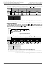
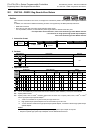
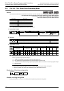
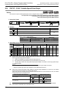
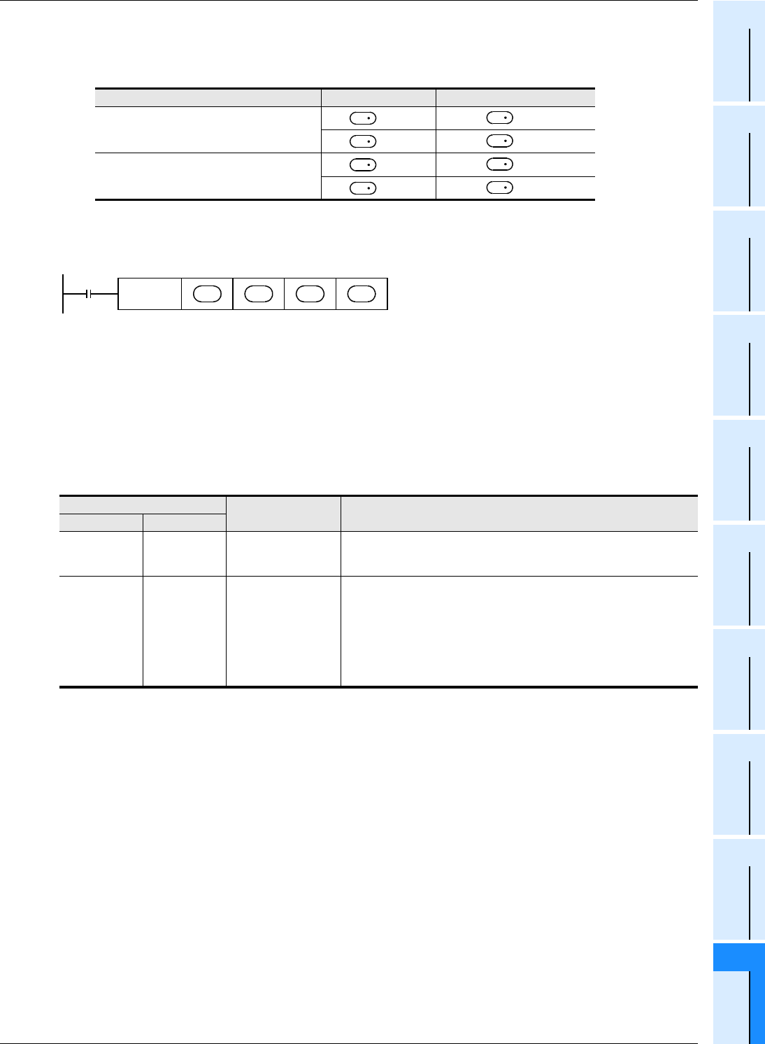
S2 : When using a special high speed output adapter for the pulse output destination in an FX3U PLC, the rotation
direction signal must be used by the following table output.
When using a built-in transistor output for the pulse output destination in an FX
3U/FX3UC PLC, the rotation
direction signal must use transistor output.
S3:"D.b" cannot be indexed with index registers (V and Z).
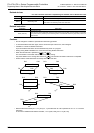
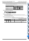
Explanation of function and operation
Caution on writing during RUN
During RUN, avoid writing while the DVIT (FNC151) instruction is executed (that is, while a pulse is output).
Note that if writing is executed during RUN to a circuit block including the FNC151 instruction while pulses are output,
the PLC decelerates and stops pulse output.
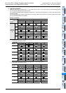
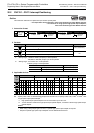
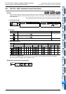
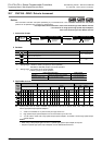
Function change depending on the version
The functions of FNC151 instruction are changed depending on the version as shown in the table below.
→ For explanation of the instruction and the contents of function change,
refer to the Positioning Control Edition.
Special high speed output adapter No. Pulse output Rotation direction output
No. 1 (1st unit)
=Y000
=Y004
=Y001
=Y005
No. 2 (2nd unit)
=Y002
=Y006
=Y003
=Y007
Applicable version
Item Outline of function
FX3U FX3UC
Ver.2.20 or later Ver.1.30 or later
Interrupt input signal
specification function
When M8336 is set to ON, the interrupt input signal corresponding to Y000
to Y003 is changed to an input number (X000 to X007) specified by D8336.
When using a transistor output in the main unit, Y003 cannot be specified.
Ver.2.20 or later Ver.2.20 or later User interrupt mode
When "8" is specified by D8336 to the interrupt input signal corresponding
to Y000 to Y003 and M8336 is set to ON, the interrupt input signal is
changed to a special auxiliary relay. When this changed special auxiliary
relay is set to ON from OFF in an input interrupt program, the PLC starts the
interrupt operation. When this function is used, however, the logic of the
interrupt input cannot be inverted.
In addition, when using a transistor output in the main unit, Y003 cannot be
specified.
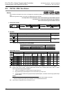
D
1
D
2
D
1
D
2
D
1
D
2
D
1
D
2
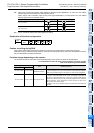
Command
input
FNC151
DVIT
S
2
S
1
D
1
D
2