


536
FX3G/FX3U/FX3UC Series Programmable Controllers
Programming Manual - Basic & Applied Instruction Edition
19 Data Operation 2 – FNC140 to FNC149
19.4 FNC143 – UNI / 4-bit Linking of Word Data
19.4 FNC143 – UNI / 4-bit Linking of Word Data
Outline
This instruction combines the low-order 4 bits of consecutive 16-bit data.
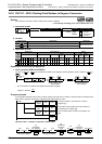
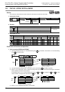
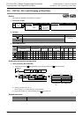
1. Instruction format
2. Set data
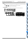
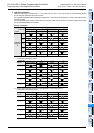
3. Applicable devices
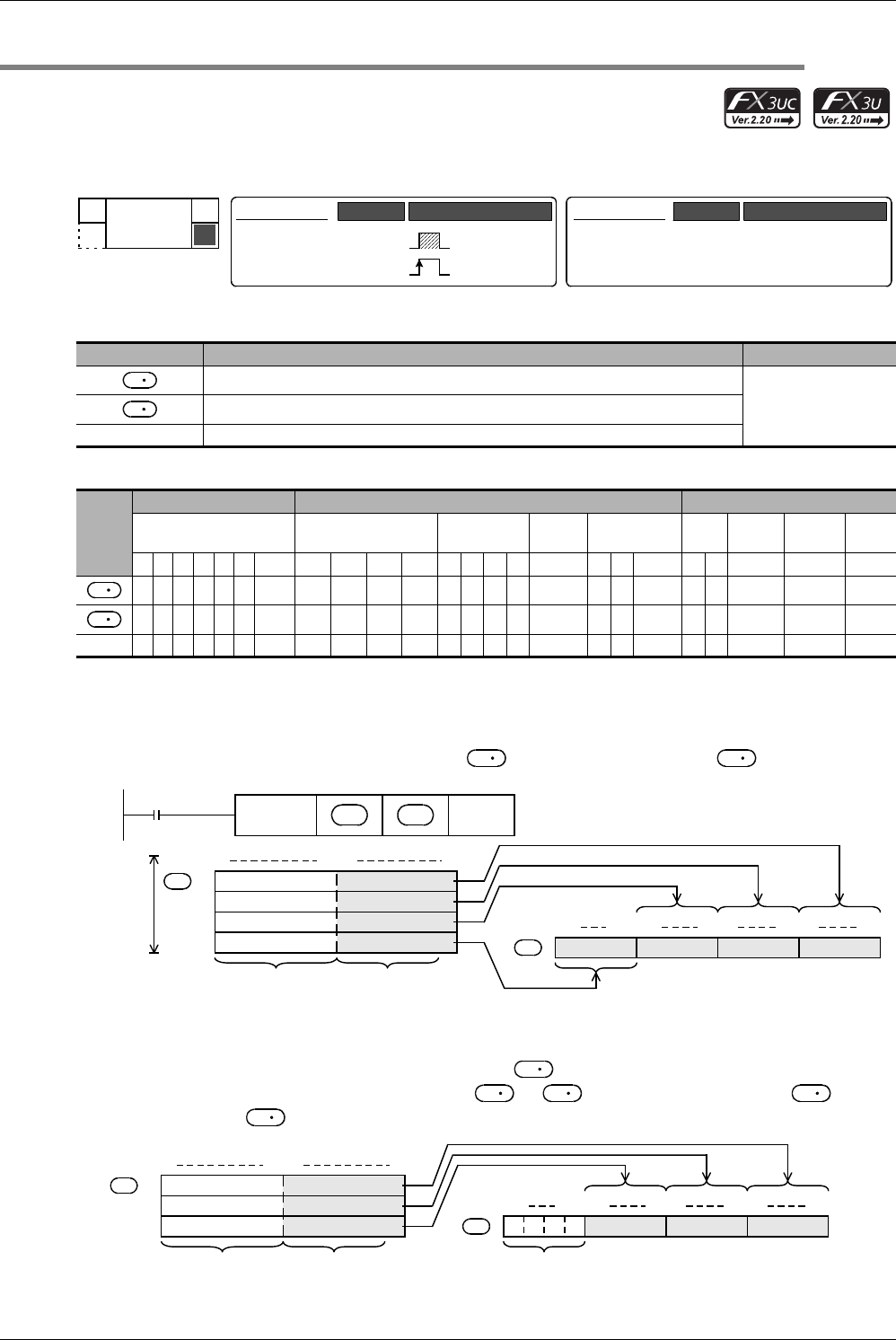
Explanation of function and operation
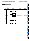
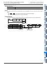
1. 16-bit operation (UNI/UNIP)
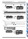
1) The low-order 4 bits of "n" 16-bit data starting from are combined, and stored in as shown below.
2) Specify a number 1 to 4 in "n".
In the case of "n = 0", UNI instruction is not executed.
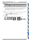
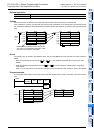
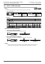
3) In the case of "1 ≤ n ≤ 3", the high-order {4 × (4-n)} bits of are set to "0".
For example, when "n" is "3", the low-order 4 bits of to +2 are stored in b0 to b11 of , and the
high-order 4 bits of are set to "0".
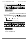
Operand type Description Data type
Head device number storing data to be combined
16-bit binary
Device number storing combined data
n Number of data to be combined (0 to 4, When "n" is "0", UNI instruction is not executed.)
Oper-
and
Type
Bit Devices Word Devices Others
System User Digit Specification System User
Special
Unit
Index
Con-
stant
Real
Number
Charac-
ter String
Pointer
XYMTCSD.b KnX KnY KnM KnS T C D R U\G VZModifyKH E ""P
3333 3
3333 3
n 33 33
P
FNC 143
UNI
−
−
Mnemonic Operation Condition
16-bit Instruction
7 steps
UNI
UNIP
Mnemonic Operation Condition
Continuous
Operation
Pulse (Single)
Operation
32-bit Instruction
S
D
S
D
S
D
Low-order 4 bits
Low-order 4 bits
Low-order 4 bits
Low-order 4 bits
Command
input
FNC143
UNIP
S
D
n
b15 b4 b3 b0
S
+0
1
2
Ignored
D
"n"
points
3
Combined data
b15 b12b11 b8 b7 b4 b3 b0
D
S
S
D
D
Low-order 4 bits
Low-order 4 bits
Low-order 4 bits
b15 b4 b3 b0
S
+0
+1
+2
Ignored
D
Combined data
b15 b12b11 b8 b7 b4 b3 b0
When "n" is "3", b12
to b15 are set to "0".
0000