


106
FX3G/FX3U/FX3UC Series Programmable Controllers
Programming Manual - Basic & Applied Instruction Edition
4 Devices in Detail
4.7 High Speed Counter [C] (FX3U/FX3UC PLC)
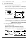
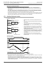
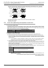
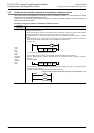
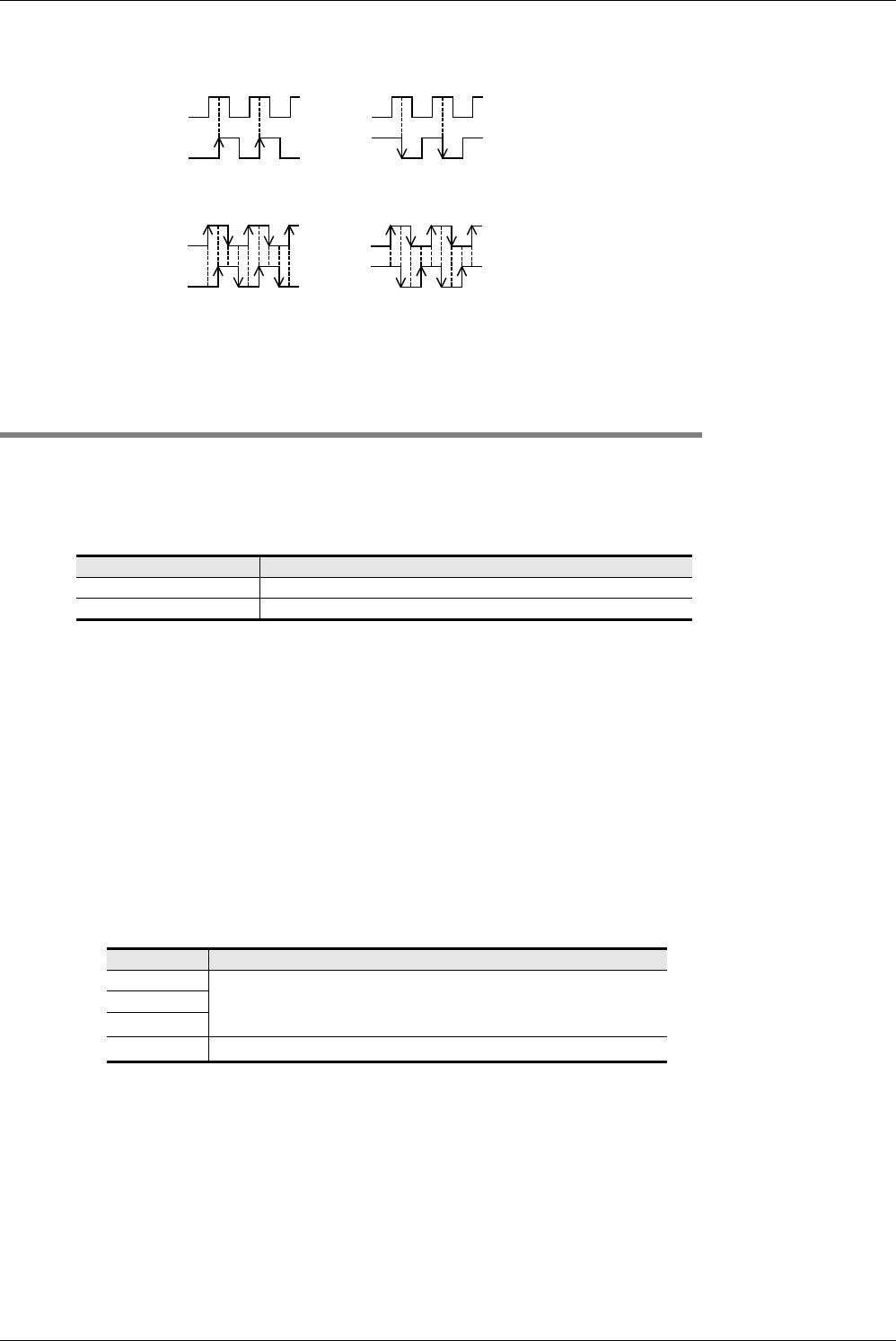
• A 2-phase encoder generates outputs for the A phase and B phase by a phase difference of 90°. With these
outputs, a high speed counter automatically executes up-count and down-count as shown in the figure below.
- When the counter is operating at the 1 edge count
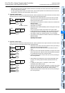
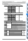
- When the counter is operating at the 4 edge count
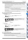
• The down/up-count operation of C251 to C255 can be checked with M8251 to M8255.
ON status: Down-counting
OFF status: Up-counting
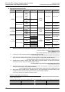
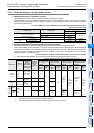
4.7.4 Current value update timing and comparison of current value
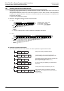
1. Current value update timing
A high speed counter executes up-count or down-count when a pulse is input to its input terminal, but the current value
is updated at the timing shown in the table below. When using the current value of a hardware counter in a MOV,
CMP or applied instruction such as the comparison instruction, special care must be taken since the current value
update timing is affected by the ladder scans as shown in the table.
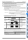
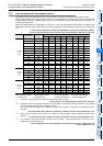
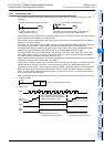
2. Comparison of the Current value
The following two methods are available to compare and output the current value of a high speed counter.
1) Using the comparison instruction (CMP), zone comparison instruction (ZCP) or comparison contact instruction
When the comparison result is necessary during counting operation
*1
, comparison may be executed in the main
program if the HCMOV instruction is used just before the comparison instruction (CMP or ZCP) or comparison
contact instruction.
*1. If it is necessary to execute comparison to update an output contact with the high-speed counter's
changing value, use comparison instructions for high speed counters (HSCS, HSCR, HSZ or HSCT).
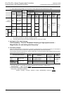
2) Using comparison instructions for high speed counters (HSCS, HSCR, HSZ or HSCT)
The comparison instructions for high speed counters (HSCS, HSCR, HSZ and HSCT) execute a comparison and
output the comparison result during high speed counting. The number of times these instructions can be used is
limited as shown in the table below.
When an output relay is specified for the comparison result, the comparison result is directly updated at the ON/
OFF status of the output regardless of the output refresh by END instruction.
Mechanical operation delay (about 10 ms) cannot be avoided in a relay output type PLC. Use a transistor output
type PLC.
*1. When HSZ or HSCT instruction is used, the maximum response frequency and total frequency of all
software counters are affected.
→ For the maximum response frequency and total frequency of software counters,
refer to Subsection 4.7.10.
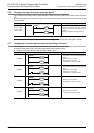
Current value update timing
Hardware counter When OUT or HCMOV instruction is executed for the counter
Software counter Every time a pulse is input
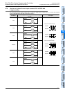
Instruction Limitation in number of instruction
HSCS
Can be used up to 32 times including HSCT instruction.
HSCR
HSZ
*1
HSCT
*1
Can be used only once.
A phase
B phase
+1
+1
Up-counting
A phase
B phase
−
1
−
1
Down-counting
A phase
B phase
+1
Up-counting
+1 +1 +1 +1
+1 +1 +1 +1
A phase
B phase
−
1
Down-counting
−
1
−
1
−
1
−
1
−
1
−
1
−
1
−
1