


378
FX3G/FX3U/FX3UC Series Programmable Controllers
Programming Manual - Basic & Applied Instruction Edition
13 High Speed Processing – FNC 50 to FNC 59
13.9 FNC 58 – PWM / Pulse Width Modulation
Cautions
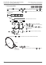
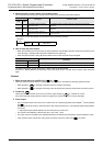
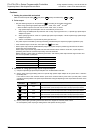
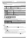
1. Setting the pulse width and period
Make sure that the pulse width and period satisfy the relationship " ≤ ".
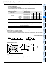
2. Pulse output
• Only the following outputs can be specified in according to the system configuration.
- When using special high speed output adapters
*1
: Y000, Y001, Y002
*2
, or Y003
*2
- When transistor outputs in the main unit are used: Y000, Y001, or Y002
*3
*1. High-speed output special adapters can be connected only to FX3U PLC.
When using the PWM (FNC 58) instruction with a relay output type FX
3U PLC, a special high speed output
adapter is required.
*2. When specifying Y002 or Y003 on a special high speed output adapter, a second special high speed output
adapter is required.
*3. Y002 is not available in 14-point and 24-point type FX
3G PLC.
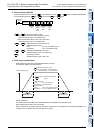
• The pulse output is controlled by interrupt processing not affected by the sequence program (operation cycle).
• If the command input is set to OFF, the output from turns OFF.
• While a pulse output monitor (BUSY/READY) flag is ON, a pulse output or positioning instruction for the same
output relay cannot be executed.
While a pulse output monitor flag is ON even after the instruction drive contact is set to OFF, a pulse output or
positioning instruction for the same output relay cannot be executed.
Before executing a pulse output or positioning instruction, wait until the pulse output monitor flag turns OFF and
one or more operation cycles pass.
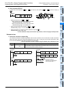
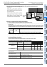
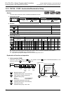
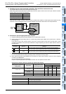
3. Cautions on using special high speed output adapters
1) Outputs of special high speed output adapters work as differential line drivers.
2) Set the pulse output type setting switch of a special high speed output adapter to the "pulse chain + direction"
(PLSxDIR) side.
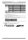
If the switch is set to the "forward rotation pulse chain reverse rotation pulse chain" (FPxRP) side, normal
operations are not possible. The pulse output destination changes depending on the output status as shown in the
table below.
3) Set the pulse output type setting switch while the PLC is stopped or while the power is OFF.
Do not adjust the pulse output type setting switch while pulses are being output.
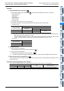
Pulse output destination device Pulse output monitor flag
Y000 M8340
Y001 M8350
Y002 M8360
Y003 M8370
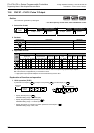
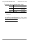
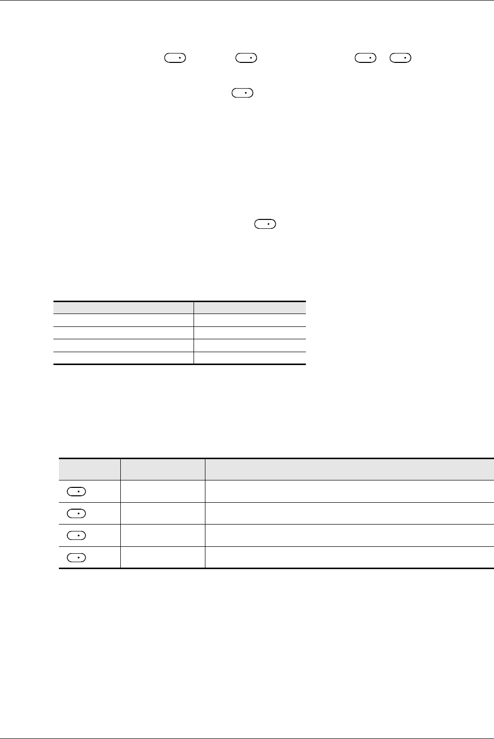
Pulse output
destination
Output affecting
operation
Operation
= Y000
Y004
While Y004 is ON, pulses are output from Y000 on the high speed output adapter.
While Y004 is OFF, pulses are output from Y004 on the high speed output adapter.
= Y001
Y005
While Y005 is ON, pulses are output from Y001 on the high speed output adapter.
While Y005 is OFF, pulses are output from Y005 on the high speed output adapter.
= Y002
Y006
While Y006 is ON, pulses are output from Y002 on the high speed output adapter.
While Y006 is OFF, pulses are output from Y006 on the high speed output adapter.
= Y003
Y007
While Y007 is ON, pulses are output from Y003 on the high speed output adapter.
While Y007 is OFF, pulses are output from Y007 on the high speed output adapter.
S
1
S
2
S
1
S
2
D
D
D
D
D
D