


251
FX3G/FX3U/FX3UC Series Programmable Controllers
Programming Manual - Basic & Applied Instruction Edition
9 Move and Compare – FNC 10 to FNC 19
9.5 FNC 14 – CML / Complement
1
Introduction
2
Overview
3
Instruction
List
4
Devices
in Detail
5
Specified the
Device &
Constant
6
Before
Programming
7
Basic
Instruction
8
FNC00-FNC09
Program Flow
9
FNC10-FNC19
Move & Compare
10
FNC20-FNC29
Arith. & Logic
Operation
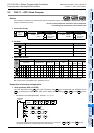
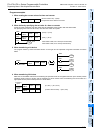
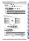
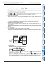
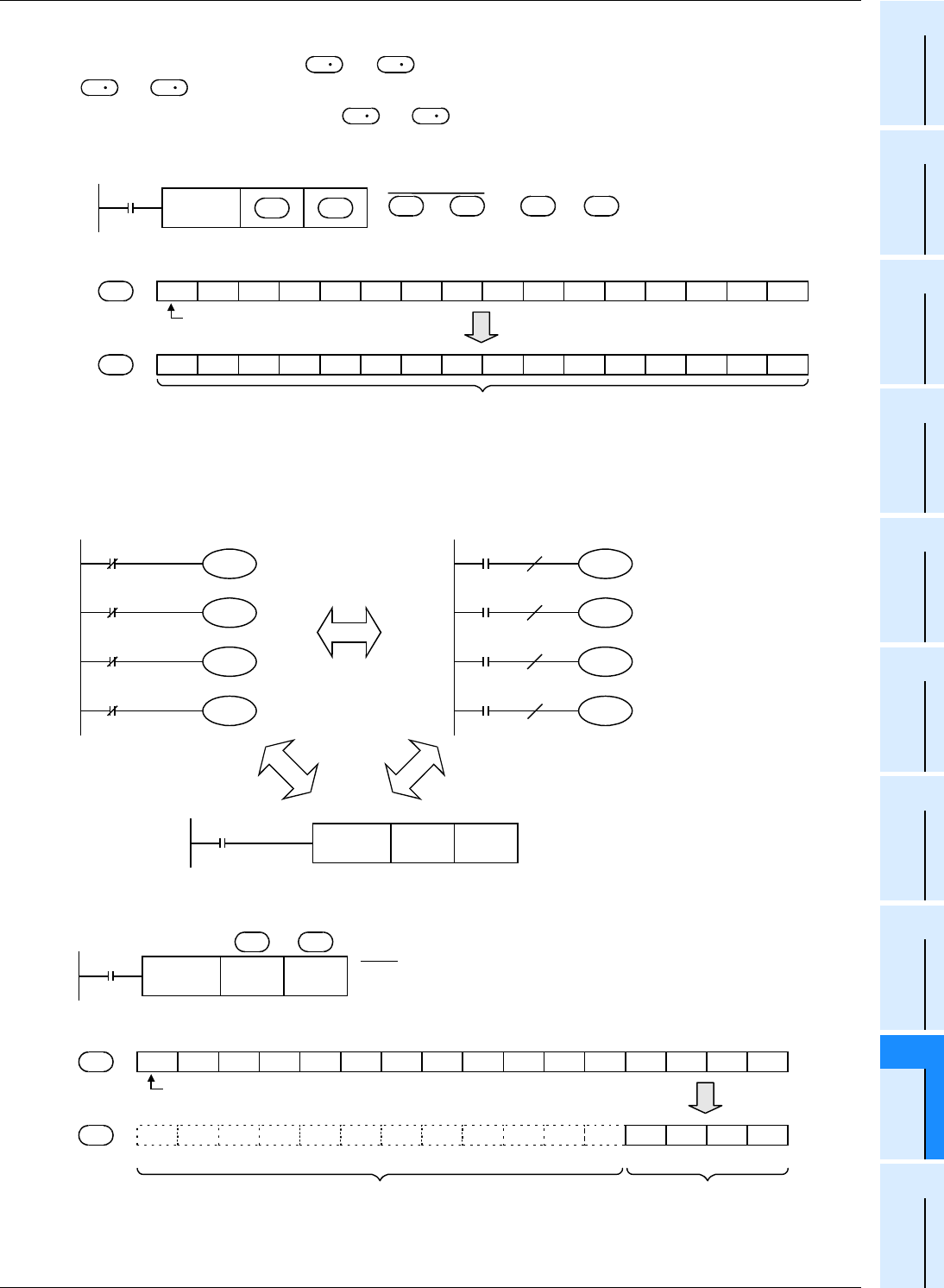
2. 32-bit operation (DCML and DCMLP)
Each bit of devices specified as [ +1, ] is inverted (from 0 to 1 or from 1 to 0), and then transferred to
[+1, ].
• When a constant (K) is specified as [ +1, ], it is automatically converted into binary.
• This operation is useful when a logically inverted output is required as an output from a PLC.
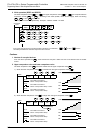
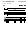
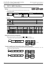
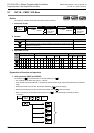
Program examples
1. When receiving an inverted input
The sequence program shown below can be written by CML instruction.
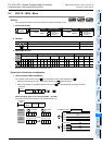
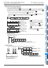
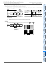
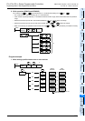
2. When four bits are specified for a device with digit specification
S
S
D
D
S
S
FNC 14
DCML
→
+1, +1,
010111001010101
0 1 0 1 0 1 0 1 1 0 0 0 1 0 1
b31 b30 b29 b28 b27 b26 b25 to b7 b6 n5 b4 b3 b2 b1 b0
Sign bit (0: Positive, 1: Negative)
Inverted data is transferred.
When command contact turns ON
S
D
S
S
D
D
S
D
Command
input
FNC 14
CML
K1X000 K1M0
X000
X001
X002
X003
M 0
M 1
M 2
M 3
X000
X001
X002
X003
M 0
M 1
M 2
M 3
M8000
RUN monitor
Y017
Do not change.
0101010101010101
0 1 0 1
Y016 Y015 Y014 Y013 Y012 Y011 Y010 Y007 Y006 Y005 Y004 Y003 Y002 Y001 Y000
Inverted data is
transferred.
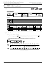
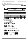
X000 = ON
D 0
K1Y000
Y015 b14 b13 b12 b11 b11 b9 b8 b7 b6 n5 b4 b3 b2 b1 b0
Sign bit (0: Positive, 1: Negative)
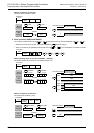
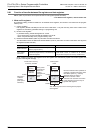
S
D
X000
FNC 14
CML
D 0 K1Y000
(D 0)
→
(K1Y000)
S
D