


103
FX3G/FX3U/FX3UC Series Programmable Controllers
Programming Manual - Basic & Applied Instruction Edition
4 Devices in Detail
4.7 High Speed Counter [C] (FX3U/FX3UC PLC)
1
Introduction
2
Overview
3
Instruction
List
4
Devices
in Detail
5
Specified the
Device &
Constant
6
Before
Programming
7
Basic
Instruction
8
FNC00-FNC09
Program Flow
9
FNC10-FNC19
Move & Compare
10
FNC20-FNC29
Arith. & Logic
Operation
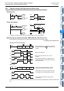
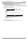
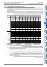
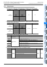
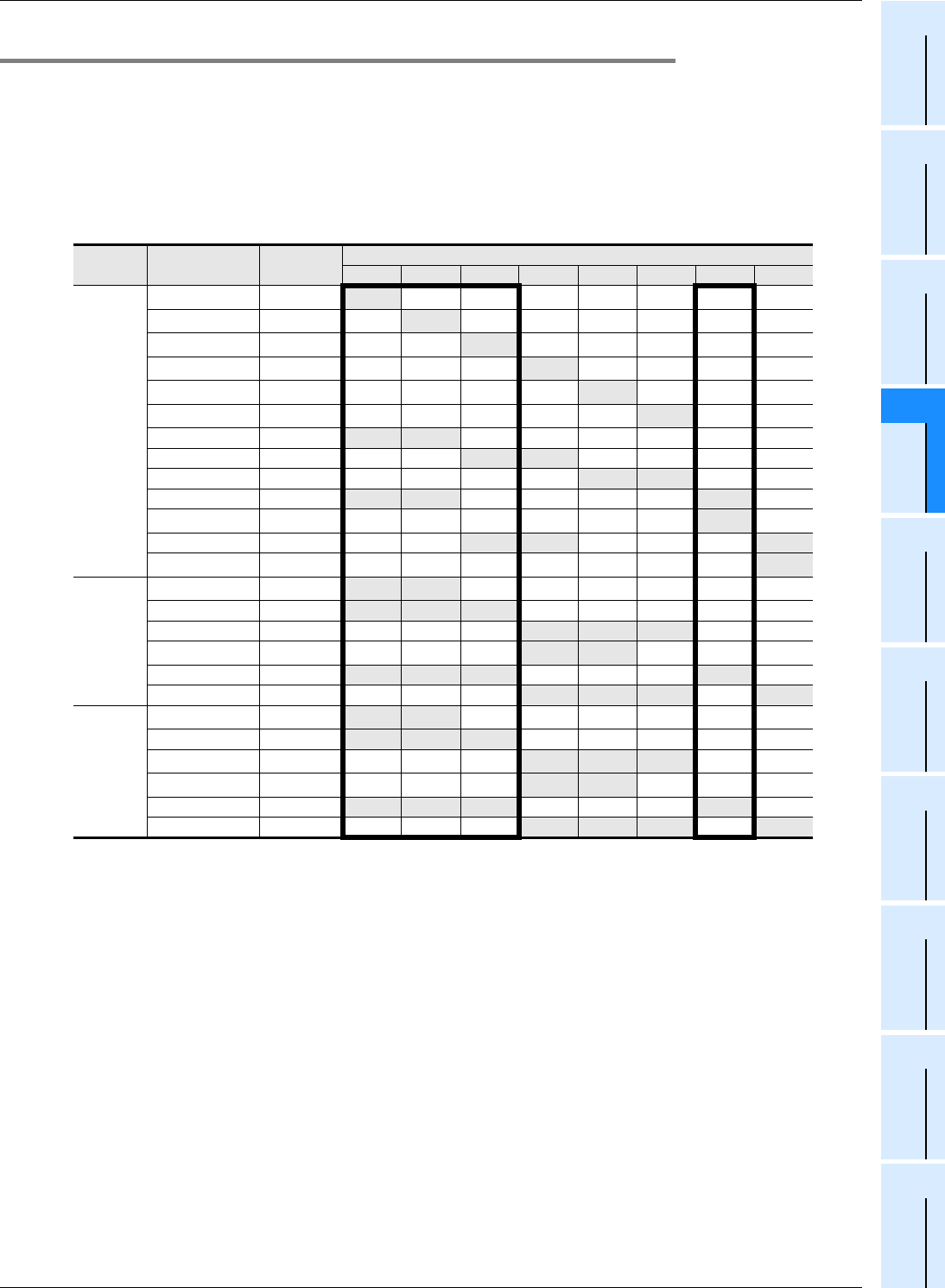
4.7.2 Input assignment for high speed counters
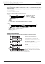
Inputs X000 to X007 are assigned as shown in the table below according to each high speed counter number.
When a high speed counter is used, the filter constant of a corresponding input number in the main unit automatically
changes (X000 to X005: 5 µs, X006 and X007: 50 µs). Input terminals not used for high speed counters, however, can
be used as general inputs.
When FX
3U-4HSX-ADP unit is connected to an FX3U PLC, input terminals inside bold-line frames in the table below
are assigned to the first FX
3U-4HSX-ADP unit, and other input terminals are assigned to the second FX3U-4HSX-ADP
unit.
→ For the input specifications of the FX
3U-4HSX-ADP, refer to the FX3U Hardware Edition.
→
For the input specifications of the main unit, refer to the Hardware Edition of the main unit
.
H/W: Hardware counter S/W: Software counter U: Up-counting input D: Down-counting input
A: A phase input B: B phase input R: External reset input S: External start input
*1. Cautions on wiring should be considered for these high speed counters.
→ For the wiring, refer to the Hardware Edition of the main unit.
*2. Hardware counters are switched to software counters when a comparison set/reset instruction for high speed
counter (DHSCS, DHSCR, DHSZ or DHSCT) is used.
The counter C253 is switched to a software counter when the logic of the external reset input signal is
reversed.
→ For the condition under which it is handled as a software counter, refer to Subsection 4.7.9.
*3. When a special auxiliary relay is driven in a program, the input terminals and their associated functions are
switched.
→ For the method to use a software counter as a hardware counter, refer to Subsection 4.7.7.
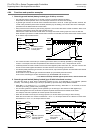
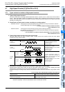
*4. In a 2-phase 2-count input counter, the edge count is usually 1. But the edge count can be set to 4 by
combining a special auxiliary relay.
→ For the method on how to use a 2-phase 2-count input counter with on edge count of 4,
refer to Subsection 4.7.8.
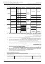
Counter No.
Classifica-
tion
Input terminal assignment
X000 X001 X002 X003 X004 X005 X006 X007
1-phase
1-count
input
C235
*1
H/W
*2
U/D
C236
*1
H/W
*2
U/D
C237
*1
H/W
*2
U/D
C238
*1
H/W
*2
U/D
C239
*1
H/W
*2
U/D
C240
*1
H/W
*2
U/D
C241 S/W
U/D R
C242 S/W
U/D R
C243 S/W
U/D R
C244 S/W
U/D R S
C244(OP)
*3
H/W
*2
U/D
C245 S/W
U/D R S
C245(OP)
*3
H/W
*2
U/D
1-phase
2-count
input
C246
*1
H/W
*2
U D
C247 S/W
U D R
C248 S/W
U D R
C248(OP)
*1*3
H/W
*2
U D
C249 S/W
U D R S
C250 S/W
U D R S
2-phase
2-count
input*
4
C251
*1
H/W
*2
A B
C252 S/W
A B R
C253
*1
H/W
*2
A B R
C253(OP)
*3
S/W A B
C254 S/W
A B R S
C255 S/W
A B R S