


137
FX3G/FX3U/FX3UC Series Programmable Controllers
Programming Manual - Basic & Applied Instruction Edition
4 Devices in Detail
4.10 Extension Register [R] and Extension File Register [ER]
1
Introduction
2
Overview
3
Instruction
List
4
Devices
in Detail
5
Specified the
Device &
Constant
6
Before
Programming
7
Basic
Instruction
8
FNC00-FNC09
Program Flow
9
FNC10-FNC19
Move & Compare
10
FNC20-FNC29
Arith. & Logic
Operation
4.10.7 Cautions on using extension file registers
1. Cautions on writing data to extension file registers (FX3U/FX3UC PLC)
Because extension file registers are stored in the flash memory inside a memory cassette, pay attention to the
following points:
• When writing data to extension file registers by SAVER instruction
Initialize sectors to be written before executing this instruction. After initialization, store data to be written to
extension registers.
In FX
3UC PLCs Ver.1.30 or later, it is not necessary to initialize sectors to be written when using RWER instruction.
• When writing data to extension file registers by LOGR instruction
Initialize sectors to be written before starting to log data.
• When using INITR instruction
This instruction initializes the contents of specified extension registers and extension file registers.
When initializing only extension file registers by this instruction, make sure to temporarily move the contents of
extension registers to unused extension registers or unused data registers before executing this instruction.
When initializing only extension file registers in FX
3UC PLCs Ver.1.30 or later, use INITER instruction.
2. Initialization of extension file registers
Because the contents of extension file registers are stored in the memory cassette or built-in EEPROM, use the data
clear operation in a sequence program or GX Developer to initialize them.
For writing data to extension file registers in FX
3U
/FX3UC PLCs, it is necessary to initialize the target area to be written
in advance.
For writing data to extension file registers in FX
3G PLCs, it is not necessary to initialize the target area to be written in
advance.
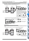
1) When initializing extension file registers in a program (required only in FX
3U/FX3UC PLCs)
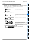
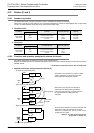
a) Initializing only extension file registers in sector units [Ver.1.30 or later]
Example: When initializing ER0 to ER4095 (initializing two sectors starting from ER0)
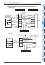
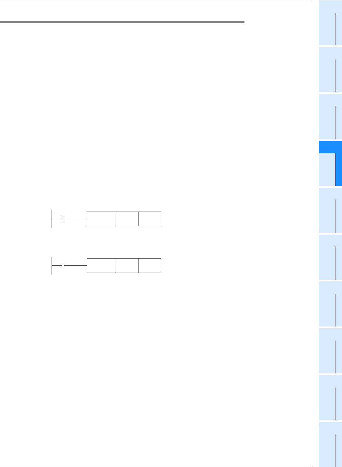
b) Initializing extension registers and extension file registers in sector units
Example: When initializing R0 to R4095 and ER0 to ER4095 (initializing two sectors starting from R0 and
ER0)
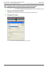
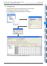
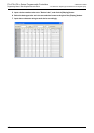
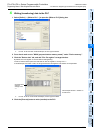
2) When initializing extension file registers using GX Developer
Select [Online] → [Clear PLC memory...] in GX Developer, and clear [Data device].
This operation initializes the contents of timers, counters, data registers, file registers and extension registers.
3. Allowable number of writes to the memory
Note the following cautions on access to extension file registers.
•In FX
3U/FX3UC PLCs
Data can be written to the memory cassette (flash memory) up to 10,000 times.
Every time the INITR (FNC292), RWER (FNC294) or INITER (FNC295) instruction is executed, it is counted as a
write to the memory. Make sure not to exceed the allowable number of writes.
When a continuous operation type instruction is used, data is written to the memory in every operation cycle of the
PLC. For preventing this, make sure to use a pulse operation type instruction.
Execution of the LOADR (FNC290), SAVER (FNC291) or LOGR (FNC293) instruction is not counted as a write to
the memory. However, it is necessary to initialize the writing target sector before executing the SAVER (FNC291)
or LOGR (FNC293) instruction.
Every time the INITR (FNC292)or INITER (FNC295) instruction is executed, it is counted as a write to the memory.
Make sure not to exceed the allowable number of writes.
•In FX
3G PLCs
Data can be written to the memory cassette (EEPROM) up to 10,000 times, and to the built-in memory (EEPROM)
up to 20,000 times.
Every time the RWER (FNC294) instruction is executed, it is counted as a write to the memory. Make sure not to
exceed the allowable number of writes.
When a continuous operation type instruction is used, data is written to the memory in every operation cycle of the
PLC. For preventing this, make sure to use a pulse operation type instruction.
Execution of the LOADR (FNC290)instruction is not counted as a write to the memory.
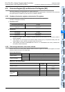
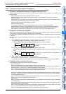
Command input
FNC 295
INITERP
R0 K2
The current value is initialized to "FFFF
H
" in ER0
to ER4095.
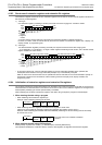
Command input
FNC 292
INITRP
R0 K2
The current value is initialized to "FFFF
H
" in R0 to R4095 and
ER0 to ER4095.