


477
FX3G/FX3U/FX3UC Series Programmable Controllers
Programming Manual - Basic & Applied Instruction Edition
16 External FX Device – FNC 80 to FNC 89
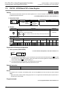
16.9 FNC 88 – PID / PID Control Loop
11
FNC30-FNC39
Rotation and
Shift
12
FNC40-FNC49
Data Operation
13
FNC50-FNC59
High Speed
Processing
14
FMC60-FNC69
Handy
Instruction
15
FNC70-FNC79
External FX I/O
Device
16
FNC80-FNC89
External FX
Device
17
FNC100-FNC109
Data
Transfer 2
18
FNC110-FNC139
Floating Point
19
FNC140-FNC149
Data
Operation 2
20
FNC150-FNC159
Positioning
Control
Cautions
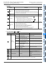
1. When using two or more PID instructions
Two or more PID instructions can be executed at the same time. (There is no limitation in the number of loops.)
However, make sure that , and other operands specified in each instruction are different to each other.
2. Number of devices occupied for parameters starting from
1) In the limit cycle method
- Twenty-nine devices are occupied from the head device specified in .
2) In the step response method
- Operation setting (ACT): When bits 1, 2 and 5 are not all "0"
Twenty-five devices are occupied from the head device specified in .
- Operation setting (ACT): When bits 1, 2 and 5 are all "0"
Twenty devices are occupied from the head device specified in .
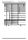
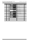
3. When specifying a device in the latched area backed up against power failure
For the output value (MV) in the PID instruction, specify a data register (D) outside the latched area.
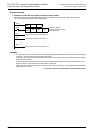
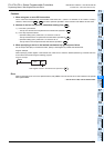
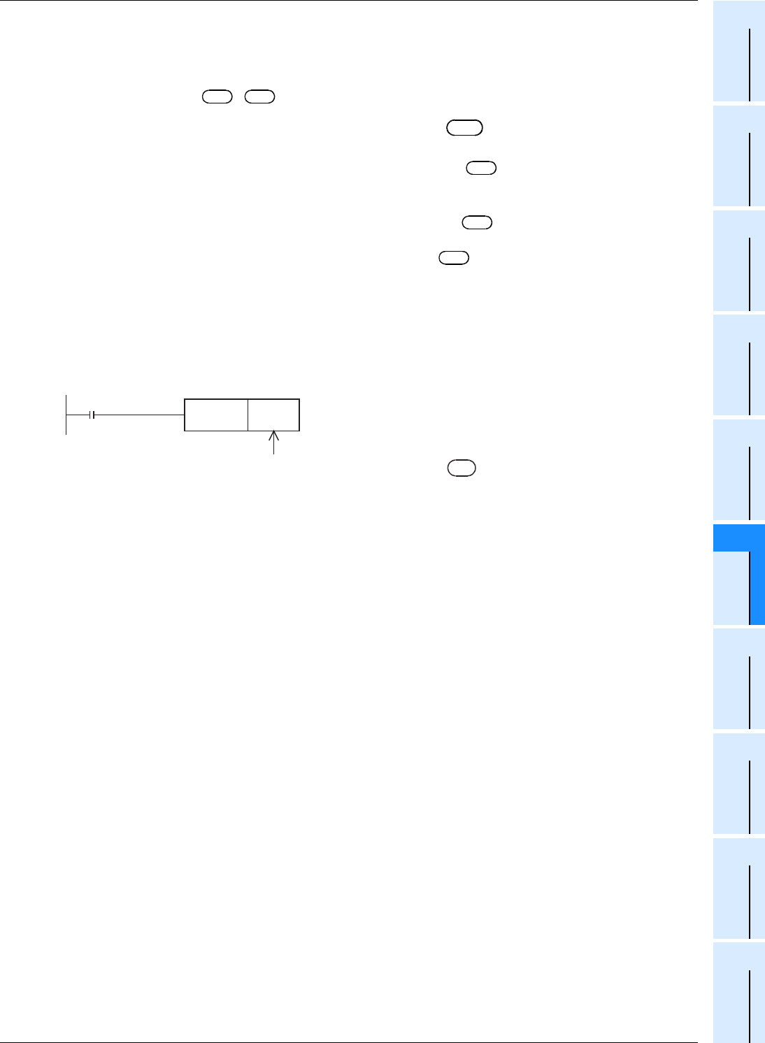
Program example
When specifying a data register in the latched area, make sure to clear the latched (backed up) contents when the
PLC mode is set to RUN using the following program.
Error
When an operation error occurs, the special auxiliary relay M8067 turns ON, and the error code is stored in the special
data register D8067.
→ For the error code, refer to Section 38.4.
S
3
D
S
3
S
3
S
3
S
3
M8002
Initial pulse
RST D***
Program example
Data register number in the latched area specified in
D