


101
FX3G/FX3U/FX3UC Series Programmable Controllers
Programming Manual - Basic & Applied Instruction Edition
4 Devices in Detail
4.7 High Speed Counter [C] (FX3U/FX3UC PLC)
1
Introduction
2
Overview
3
Instruction
List
4
Devices
in Detail
5
Specified the
Device &
Constant
6
Before
Programming
7
Basic
Instruction
8
FNC00-FNC09
Program Flow
9
FNC10-FNC19
Move & Compare
10
FNC20-FNC29
Arith. & Logic
Operation
4.7 High Speed Counter [C] (FX3U/FX3UC PLC)
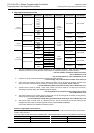
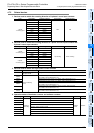
4.7.1 Types and device numbers of high speed counters
1. Types of high speed counters
The main unit has built-in 32-bit high speed bi-directional counters (1-phase 1-count, 1-phase 2-count and 2-phase 2-
count). These high speed counters are classified into hardware type or software type according to the counting
method. Some high speed counters are capable of using an external reset input terminal and an external start input
terminal (for counting start).
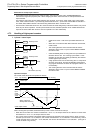
2. Classification of high speed counters according to counting method
• Hardware counters: These types of counters execute counting by hardware, but may be switched to software
counters depending on the operating condition.
→ For the condition handled as software counters,
refer to Subsection 4.7.9.
• Software counters: These types of counters execute counting as CPU interrupt processing.
It is necessary to use each software counter within both limitations of maximum response
frequency and total frequency.
→ For the limitation of response frequency depending on the total frequency,
refer to Subsection 4.7.10.
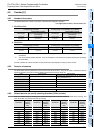
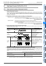
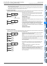
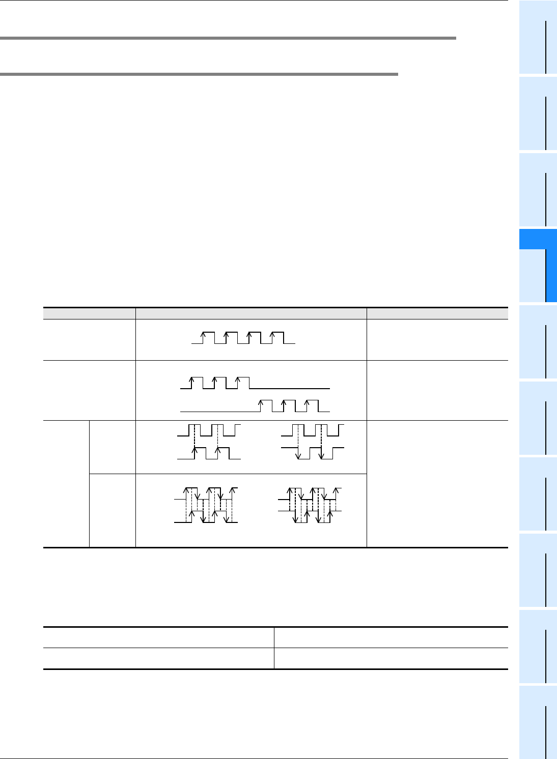
3. Types of high speed counters and input signal forms
The table below shows the types (1-phase 1-count, 1-phase 2-count and 2-phase 2-count) and input signals
(waveforms) of high speed counters.
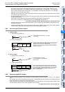
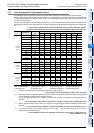
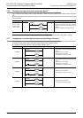
4. Cautions on counterpart equipment connected to high speed counter inputs
General-purpose inputs X000 to X007 are used for high speed counter inputs. An encoder
*1
adopting the output
method shown in the table below can be connected depending on the connected terminal.
Encoders adopting the voltage output method and absolute encoders cannot be connected to high speed counter
inputs.
→ For the wiring, refer to the Hardware Edition of the main unit.
*1. A rotary encoder adopting the output method shown above may not operate correctly depending on the
electrical compatibility. Check the specifications before connecting an encoder.
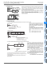
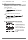
Input signal form Counting direction
1-phase
1-count input
Down-count or up-count is specified by
turning on or off M8235 to M8245.
ON: Down-counting
OFF: Up-counting
1-phase
2-count input
A counter executes up-count or down-
count as shown on the left.
The counting direction can be checked
with M8246 to M8250.
ON: Down-counting
OFF: Up-counting
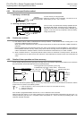
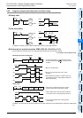
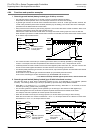
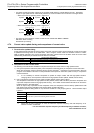
2-phase
2-count
input
1 edge
count
A counter automatically executes up-
count or down-count according to
changes in the input status of the A/B
phase as shown on the left.
The counting direction can be checked
with M8251 to M8255.
ON: Down-counting
OFF: Up-counting
4 edge
count
Output method of encoder which can be directly connected to input
terminal in main unit
Open collector transistor output method compatible with 24V DC
Output method of encoder which can be directly connected to input
terminal in FX
3U-4HSX-ADP
Differential line driver output method
(output voltage: 5V DC or less)
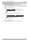
UP/DOWN
UP
DOWN
+1 +1 +1
−
1
−
1
−
1
B phase
A phase
+1
+1
Up-counting
A phase
B phase
−
1
−
1
Down-counting
A phase
B phase
+1
Up-counting
+1 +1 +1 +1
+1 +1 +1 +1
A phase
B phase
−
1
Down-counting
−
1
−
1
−
1
−
1
−
1
−
1
−
1
−
1