


593
FX3G/FX3U/FX3UC Series Programmable Controllers
Programming Manual - Basic & Applied Instruction Edition
24 Others – FNC181 to FNC189
24.4 FNC188 – CRC / Cyclic Redundancy Check
21
FNC160-FNC169
Real Time Clock
Control
22
FNC170-FNC179
External Device
23
FNC180
Alternate
Instructions
24
FNC181-FNC189
Others
25
FNC190-FNC199
Block Data
Operation
26
FNC200-FNC209
Character String
Control
27
FNC210-FNC219
Data
Operation 3
28
FNC220-FNC249
Data
Comparison
29
FNC250-FNC269
Data Table
Operation
30
FNC270-FNC274
Ex-Device
Inverter Comms
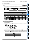
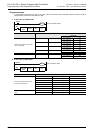
2. Related device
*1. Cleared when the PLC mode is changed from RUN to STOP.
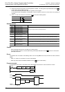
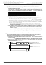
Caution
In this instruction, “X
16
+ X
15
+ X
2
+ 1” is used as a polynomial for generating the CRC value (CRC-16). There are
many other standard polynomials for generating the CRC value. Note that the CRC value completely differs if an
adopted polynomial is different.
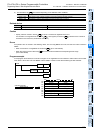
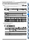
Reference: Major polynomials for generating the CRC value
Errors
An operation error is caused in the following cases; The error flag M8067 turns ON, and the error code is stored in
D8067.
• When any digits other than 4 digits are specified as or in digit specification of bit device (error code:
K6706)
• When n is outside the allowable range (1 to 256) (error code: K6706)
• When a device specified by +n-1 or +1 is outside the allowable range (error code: K6706)
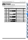
Related device Description
M8161
*1
ON CRC instruction operates in the 8-bit mode.
OFF CRC instruction operates in the 16-bit mode.
Name Polynomial
CRC-12
X
12
+ x
11
+ X
3
+ X
2
+ X + 1
CRC-16
X
16
+ X
15
+ X
2
+ 1
CRC-32
X
32
+ X
26
+ X
23
+ X
22
+ X
16
+ X
12
+ X
11
+ X
10
+ X
8
+ X
7
+ X
5
+ X
4
+ X
2
+ X + 1
CRC-CCITT
X
16
+ X
12
+ X
5
+ 1
S
D
S
D