


659
FX3G/FX3U/FX3UC Series Programmable Controllers
Programming Manual - Basic & Applied Instruction Edition
28 Data Comparison – FNC220 to FNC249
28.3 FNC240~246 – OR=, >, <, < >, <=, >= / Data Comparison
21
FNC160-FNC169
Real Time Clock
Control
22
FNC170-FNC179
External Device
23
FNC180
Alternate
Instructions
24
FNC181-FNC189
Others
25
FNC190-FNC199
Block Data
Operation
26
FNC200-FNC209
Character String
Control
27
FNC210-FNC219
Data
Operation 3
28
FNC220-FNC249
Data
Comparison
29
FNC250-FNC269
Data Table
Operation
30
FNC270-FNC274
Ex-Device
Inverter Comms
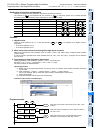
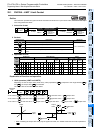
Explanation of function and operation
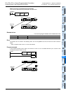
FNC240 to 246 are data comparison instructions connected to other contacts in parallel.
The contents of are compared with the contents of in binary format, and a contact becomes conductive
(ON) or non-conductive (OFF) depending on the comparison result.
Cautions
1. Negative value
When the most significant bit is "1" in the data stored in or , it is regarded as a negative value in
comparison.
• In the 16-bit operation: bit 15
• In the 32-bit operation: bit 31
2. When using 32-bit counters (including 32-bit high speed counters)
Make sure to execute the 32-bit operation (such as "ORD=", "ORD>" and "ORD<") when comparing 32-bit counters
(C200 to C255).
If a 32-bit counter is specified in the 16-bit operation (such as "ORD=", "OR>" and "OR<"), a program error or
operation error will occur.
3. Programming of data comparison instructions
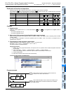
When programming in GX Developer, symbols "≤" and "≥" cannot be input.
Separate "≤" into "<" and "=", and separate "≥" into ">" and "=".
The input procedure is described below:
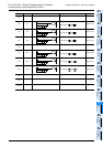
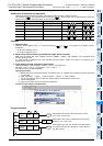
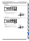
Operating procedure
a) Display the circuit program edit window, and put the cursor in a position where a data comparison instruction
is to be used.
b) Input "Instruction" → "space" → "value or device" → "space" → "value or device".
For an input example, refer to "Instruction input window in GX Developer" shown below.
c) Click the [OK] button.
d) Input other contacts and coil drive units consecutively.
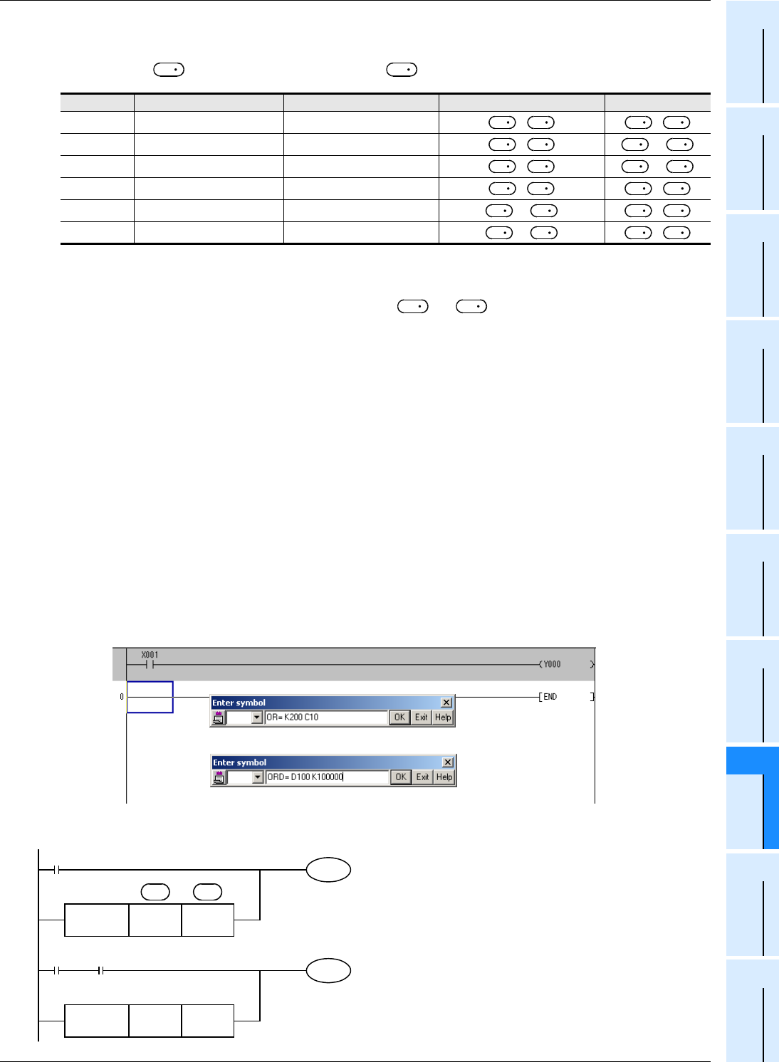
Instruction input window in GX Developer
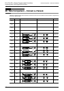
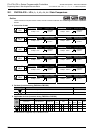
Program example
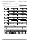
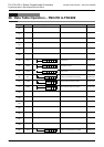
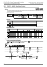
FNC No. 16-bit instruction 32-bit instruction ON condition OFF condition
240 OR= ORD=
= ≠
241 OR> ORD>
> <=
242 OR< ORD<
< >=
244 OR<> ORD<>
≠ =
245 OR<= ORD<=
<= >
246 OR>= ORD>=
>= <
S
1
S
2
S
1
S
2
S
1
S
2
S
1
S
2
S
1
S
2
S
1
S
2
S
1
S
2
S
1
S
2
S
1
S
2
S
1
S
2
S
1
S
2
S
1
S
2
S
1
S
2
S
1
S
2
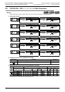
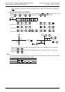
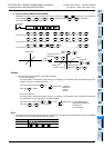
<Input example for 16-bit operation>
<Input example for 32-bit operation>
Y000
X001
K100000
FNC246
ORD>=
D100
M60
M30X002
C10
FNC240
OR=
K200
S
1
S
2
When X001 turns ON or when the current value of the
counter C10 is "200", Y000 is driven.
When X002 and M30 turn ON or when the contents of the
data registers D101 and D100 are more than "K100,000"
M60 is driven.