


375
FX3G/FX3U/FX3UC Series Programmable Controllers
Programming Manual - Basic & Applied Instruction Edition
13 High Speed Processing – FNC 50 to FNC 59
13.8 FNC 57 – PLSY / Pulse Y Output
11
FNC30-FNC39
Rotation and
Shift
12
FNC40-FNC49
Data Operation
13
FNC50-FNC59
High Speed
Processing
14
FMC60-FNC69
Handy
Instruction
15
FNC70-FNC79
External FX I/O
Device
16
FNC80-FNC89
External FX
Device
17
FNC100-FNC109
Data
Transfer 2
18
FNC110-FNC139
Floating Point
19
FNC140-FNC149
Data
Operation 2
20
FNC150-FNC159
Positioning
Control
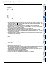
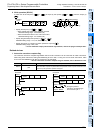
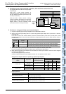
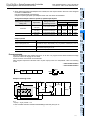
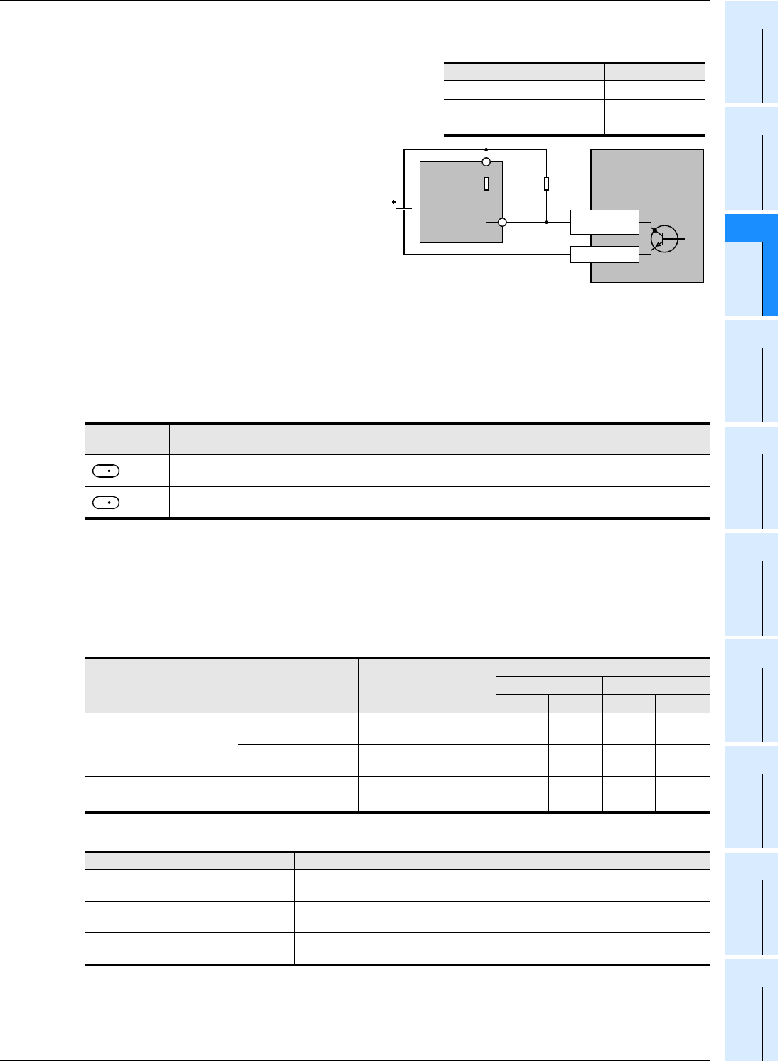
4. Handling of pulse output terminals in the FX3G, FX3U and FX3UC series main units
The outputs Y000 and Y001 are the high speed
response type.
When using a pulse output instruction or
positioning instruction, adjust the load current of
the open collector transistor output to about 10 to
100 mA (5 to 24V DC).
When the load is smaller, connect a dummy
resistor in parallel to the outside of a used output
terminal (Y000 or Y001) as shown in the circuit
diagram below so that the specified current
shown above flows in the output transistor.
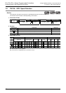
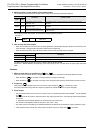
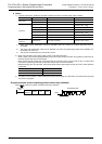
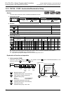
5. Cautions on using special high speed output adapters
1) Outputs of special high speed output adapters work as differential line drivers.
2) Set the pulse output type setting switch in a special high speed output adapter to the "pulse chain + direction"
(PLSxDIR) side.
If the switch is set to the "forward rotation pulse chain reverse rotation pulse chain" (FPxRP) side, normal
operations are disabled. The pulse output destination changes depending on the PLC output status as shown in
the table below.
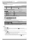
3) Set the pulse output type setting switch while the PLC is stopped or while the power is OFF.
Do not manipulate the pulse output form setting switch while pulses are being output.
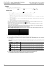
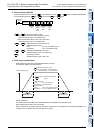
4) When special high speed output adapters are connected, the same output numbers in the main unit are assigned
as shown in the table below.
Only wire the appropriate output terminals.
Outputs in special high speed output adapters and the main unit operate as shown below.
Assignment of output numbers in special high speed output adapters
Output operation
Pulse output
destination
Output affecting
operation
Operation
= Y000
Y004
While Y004 is ON, pulses are output from Y000 in the high speed output adapter.
While Y004 is OFF, pulses are output from Y004 in the high speed output adapter.
= Y001
Y005
While Y005 is ON, pulses are output from Y001 in the high speed output adapter.
While Y005 is OFF, pulses are output from Y005 in the high speed output adapter.
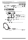
Status of output form setting
switch
Signal name
Setting name in each
positioning instruction
Output number
1st unit 2nd unit
1st axis 2nd axis 3rd axis 4th axis
"FPxRP" side
Forward rotation pulse
chain (FP)
Pulse output destination Y000 Y001 Y002 Y003
Reverse rotation pulse
chain (RP)
Rotation direction signal Y004 Y005 Y006 Y007
"PLSxDIR" side
Pulse chain Pulse output destination Y000 Y001 Y002 Y003
Direction Rotation direction signal Y004 Y005 Y006 Y007
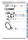
Output operation
Relay output type main unit
While instruction is activated, relevant output is ON. (LED is also ON.)
Use a special high speed adapter.
Special high speed output adapter
Operated.
Set the output frequency to "200kHz" or less.
Transistor output type main unit
Operated.
Set the output frequency to "100kHz" or less.
Item Description
Operating voltage range 5 to 24V DC
Operating current range 10 to 100 mA
Output frequency 100 kHz or less
External
power
supply
Equipment
load
resistor
Dummy
resistor
Y000
COM1
PLC
(transistor output)
[sink output]
Input circuit
D
D