


379
FX3G/FX3U/FX3UC Series Programmable Controllers
Programming Manual - Basic & Applied Instruction Edition
13 High Speed Processing – FNC 50 to FNC 59
13.9 FNC 58 – PWM / Pulse Width Modulation
11
FNC30-FNC39
Rotation and
Shift
12
FNC40-FNC49
Data Operation
13
FNC50-FNC59
High Speed
Processing
14
FMC60-FNC69
Handy
Instruction
15
FNC70-FNC79
External FX I/O
Device
16
FNC80-FNC89
External FX
Device
17
FNC100-FNC109
Data
Transfer 2
18
FNC110-FNC139
Floating Point
19
FNC140-FNC149
Data
Operation 2
20
FNC150-FNC159
Positioning
Control
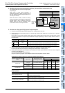
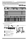
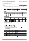
4) When special high speed output adapters are connected, the same output numbers in the main unit are assigned
as shown in the table below.
Only wire the appropriate output terminals.
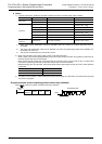
Outputs in special high speed output adapters and the main unit operate as shown below.
Assignment of output numbers in special high speed output adapters
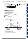
Output operation
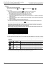
Program example
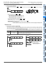
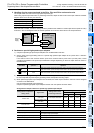
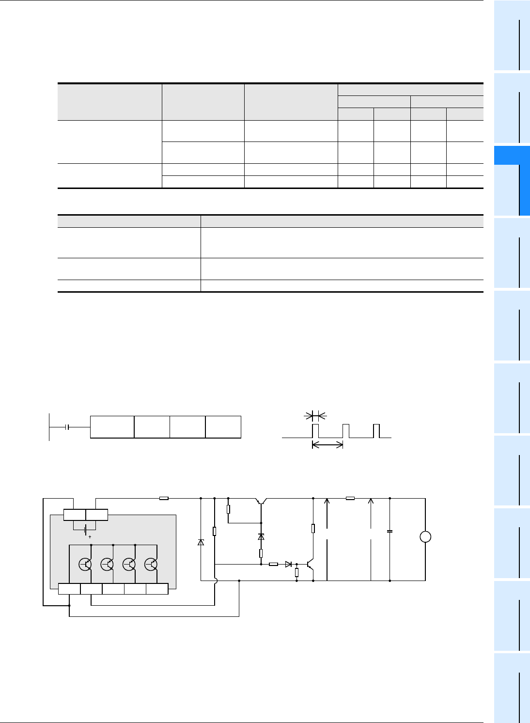
When the contents of D10 are changed ranging from "0" to "50" in the program example shown below, the average
output from Y000 will be ranging from 0 to 100%.
An error will occur if the contents of D10 exceed 50.
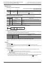
In this program example the FX
3U series main unit (sink output) is used. For wiring details, refer to the following
manual.
→ FX
3G Hardware Edition
→ FX
3U Hardware Edition
→ FX
3UC Hardware Edition
Example of smoothing circuit
R > P
τ = P(kΩ) ° C(µF) = 470ms >> T
0
The time constant of the filter should be considerably larger than the pulse cycle T0.
The ripple value "∆e" in the mean output current "e" is approximately "∆e/e ≤ T
0/τ"
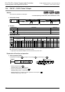
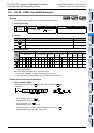
Setting status of output form
setting switch
Signal name
Setting name in each
positioning instruction
Output number
1st unit 2nd unit
1st axis 2nd axis 3rd axis 4th axis
"FPxRP" side
Forward rotation pulse
chain (FP)
Pulse output destination Y000 Y001 Y002 Y003
Reverse rotation pulse
chain (RP)
Rotation direction signal Y004 Y005 Y006 Y007
"PLSxDIR" side
Pulse chain Pulse output destination Y000 Y001 Y002 Y003
Direction Rotation direction signal Y004 Y005 Y006 Y007
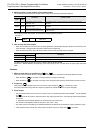
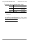
Output operation
Relay output type main unit
Do not use the PWM (FNC 58) instruction with relay-output type main units.
(Considerable output response delay may be generated, chattering may occur in
contacts, or the contact life may be shortened.)
Special high speed output adapter
Set the output frequency to "200kHz" or less.
Use a transistor output type main unit.
Transistor output type main unit Set the output frequency to "100kHz" or less.
X0
D10 K50 Y000
FNC 58
PWM
D10
50ms
Y000
Y000
COM1
Y001 Y002 Y003
PLC
510
Ω
12V
1k
Ω
E
e
V
+
C
470
µ
F
10V
5V
1k
Ω
1k
Ω
1k
Ω
R
(1k
Ω
)
P
22
Ω
24V0V