


93
FX3G/FX3U/FX3UC Series Programmable Controllers
Programming Manual - Basic & Applied Instruction Edition
4 Devices in Detail
4.5 Timer [T]
1
Introduction
2
Overview
3
Instruction
List
4
Devices
in Detail
5
Specified the
Device &
Constant
6
Before
Programming
7
Basic
Instruction
8
FNC00-FNC09
Program Flow
9
FNC10-FNC19
Move & Compare
10
FNC20-FNC29
Arith. & Logic
Operation
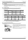
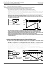
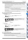
2. Retentive type
When the drive input X001 of the timer coil T250 turns ON, the current
value counter for T250 adds and counts clock pulses of 100 ms.
When the counted value becomes equivalent to the set value K345,
the output contact of the timer turns on.
Even if the drive input X001 turns OFF or the power is turned off
during counting, the timer continues counting when the operation
restarts. The retentive operating time is 34.5 seconds.
When the reset input X002 turns ON, the timer is reset and the output
contact is returned.
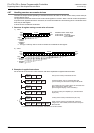
3. Potentiometer type
1) When variable analog potentiometers built in the FX3G main unit are used
Values of variable analog potentiometers built
in FX
3G PLCs as standard are stored as
numeric data in the range from 0 to 255 in the
following special registers in accordance with
the scale position.
An obtained numeric value can be specified
as the indirectly specified value for a timer to
make a variable potentiometer type analog
timer.
•VR1 → D8030 (Integer from 0 to 255)
•VR2 → D8031 (Integer from 0 to 255)
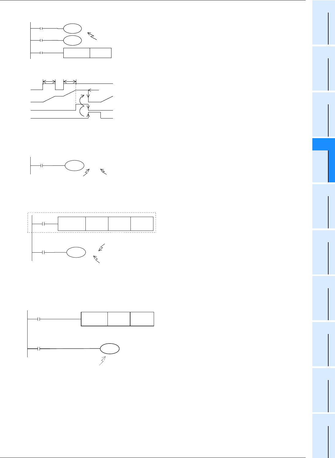
2) When variable analog potentiometers (expansion board) are used
The value of a variable analog potentiometer board
which can be built in an FX
3G PLC as an expansion
board can be obtained as numeric data in the range
from 0 to 255 in accordance with the scale position.
An obtained numeric value can be specified as the
indirectly specified value for a timer to make a
variable potentiometer type analog timer.
Use the FNC85 (VRRD) instruction to take the
value of a variable analog potentiometer into the
PLC.
→ For FNC85(VRRD), refer to Section 16.6.
Use the FNC86 (VRSC) instruction to take the value
of a variable analog potentiometer as a numeric
value in the range from 0 to 10.
→ For FNC86(VRSC), refer to Section 16.7.
X001
T250
T250
Y001
K345
Set value
(constant)
A data register
can be
specified also.
X002
RST T250
Current
value
Y001
X001
X002
Set value
t2
t1
Retentive time
t1 + t2 = 34.5 sec
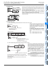
X003
T10 D08030
[Basic example]
This register stores the
value (0 to 255) of variable
analog potentiometer.
0 to 25.5 sec
FNC 22
MUL
D8031 K 2 DO (D1)
M8000
X003
T10
D 0
[Applied example]
"D8030 (VR2) value x 2" is transferred to D0 (D1).
(0 to 51 sec)
The set value range can be
changed (up to 32,767) by multiplying
the register value by "n".
RUN monitor
Do not use D1 in other programs.
VRRD
Example of application as analog time
r
The analog value of the potentiometer No. 0 is converted into
binary 8-bit data, and a numeric value in the range from 0 to 255
is transferred to D0.
In this application example, the value of D0 is used as the set
value of a timer.
volume
number
Read
destination
FNC 85
K0 D0
X000
X001
T0
D0