


433
FX3G/FX3U/FX3UC Series Programmable Controllers
Programming Manual - Basic & Applied Instruction Edition
15 External FX I/O Device – FNC 70 to FNC 79
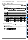
15.5 FNC 74 – SEGL / Seven Segment With Latch
11
FNC30-FNC39
Rotation and
Shift
12
FNC40-FNC49
Data Operation
13
FNC50-FNC59
High Speed
Processing
14
FMC60-FNC69
Handy
Instruction
15
FNC70-FNC79
External FX I/O
Device
16
FNC80-FNC89
External FX
Device
17
FNC100-FNC109
Data
Transfer 2
18
FNC110-FNC139
Floating Point
19
FNC140-FNC149
Data
Operation 2
20
FNC150-FNC159
Positioning
Control
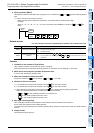
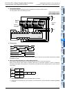
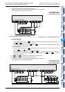
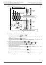
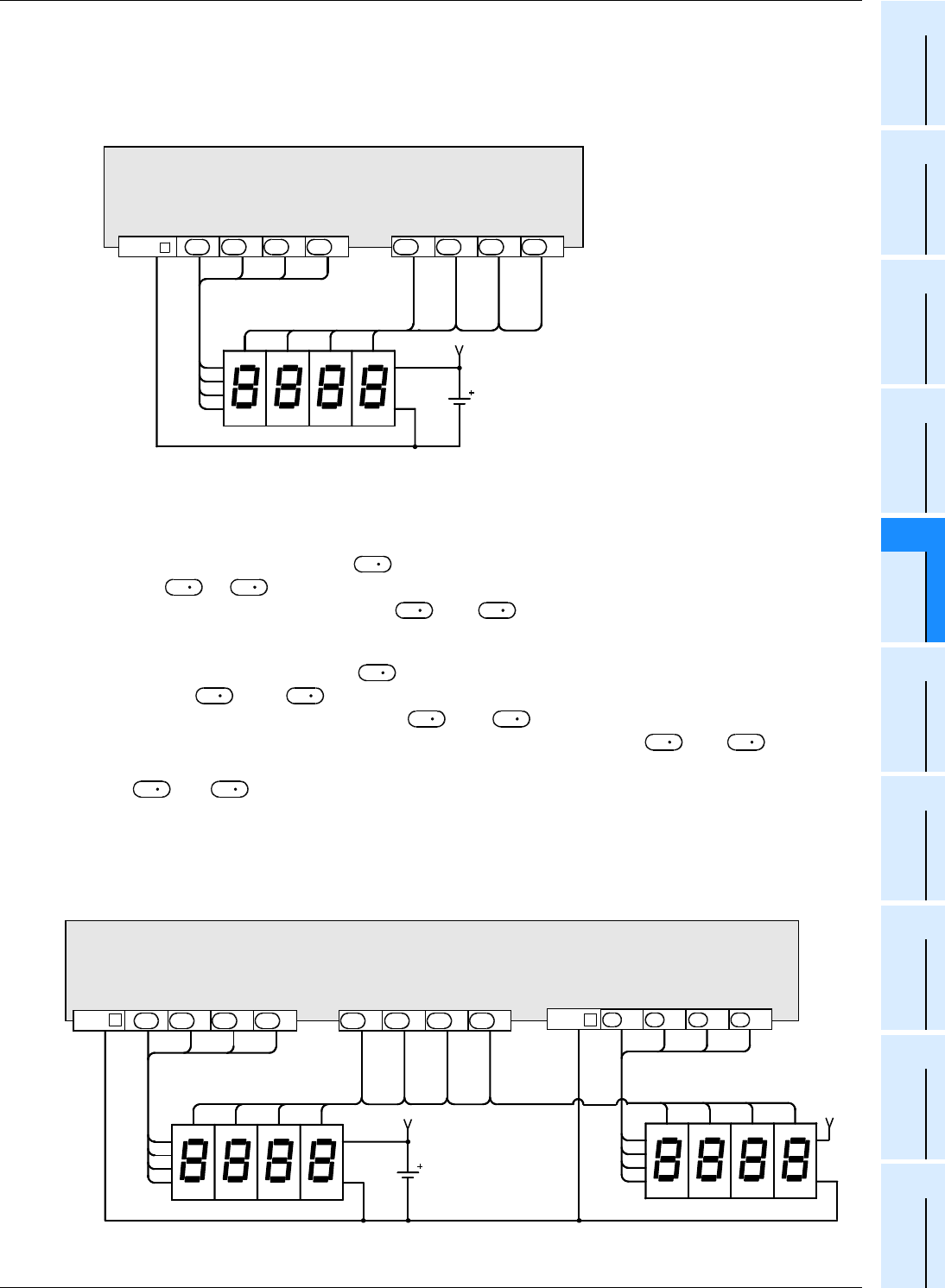
3) Example of connecting one seven-segment display unit
The figure below shows an example of the FX
3U series main unit (sink output).
For wiring details, refer to the following manuals.
→ FX
3G Hardware Edition
→ FX
3U Hardware Edition
→ FX
3UC Hardware Edition
When using two sets of 4 digits (n = K4 to K7)
→ For selection of "n", refer to Subsection 15.5.2.
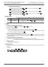
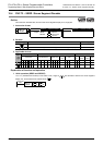
1) Data and strobe signal
a) 1st set of 4 digits
A 4-digit numeric value stored in is converted from binary into BCD, and its each digit is output in turn
from to +3 in the time division method.
The strobe signal is output in turn from +4 to +7 in the time division method also to latch the first
set of 4-digit seven-segment display unit.
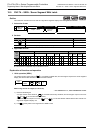
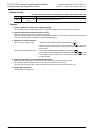
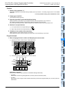
b) 2nd set of 4 digits
A 4-digit numeric value stored in +1 is converted from binary into BCD, and its each digit is output in
turn from +10 to +13 in the time division method.
The strobe signal is output in turn from +4 to +7 in the time division method also to latch the
second set of 4-digit seven-segment display unit. (The strobe signal outputs +4 to +7 are shared
by the 1st and 2nd sets.)
2) For and +1, binary data in the range from 0 to 9999 is valid.
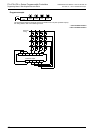
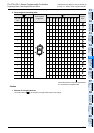
3) Example of connecting two seven-segment display units
The figure below shows an example of the FX
3U series main unit (sink output).
For wiring details, refer to the following manuals.
→ FX
3G Hardware Edition
→ FX
3U Hardware Edition
→ FX
3UC Hardware Edition
10
0
4
2
81
1
2
4
8
1st set
V+
10
1
10
2
10
3
10
3
10
2
10
1
10
0
COM
+1 +2 +3 +4 +6 +7
+5
PLC (transistor output type)
D
D
D
D
D
D
D
D
S
D
D
D
D
S
D
D
D
D
D
D
S
S
10
0
4
2
81
1
2
4
8
1st set
V+
10
1
10
2
10
3
10
3
10
2
10
1
10
0
COM +1
PLC
(transistor output type)
+2 +3 +4 +6 +7
+5
D
D
D
D
D
D
D
D
2nd set
V+
1
2
4
8
4
2
81
10
3
10
2
10
1
10
0
+10 +11 +12 +13
D
D
D
D
COM