


797
FX3G/FX3U/FX3UC Series Programmable Controllers
Programming Manual - Basic & Applied Instruction Edition
36 Interrupt Function and Pulse Catch Function
36.1 Outline
31
FNC275-FNC279
Data
Transfer 3
32
FNC280-FNC289
High Speed
Processing 2
33
FNC290-FNC299
Extension File
Register
34
FNC300-FNC305
FX
3U
-CF-ADP
35
SFC•STL
Programming
36
Interrupt
Function
37
Special Device
38
Error Code
A
Version Up
Information
B
Execution Times
36. Interrupt Function and Pulse Catch Function
This chapter explains the built-in interrupt function and pulse catch function in FX PLCs.
36.1 Outline
This section explains the function to immediately execute an interrupt program (interrupt routine) without affecting the
operation cycle of the sequence program (main) while using a interrupt function as a trigger. The delay by operation
cycle and machine operation affected by uneven time intervals in normal sequence program process can be improved.
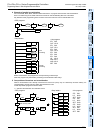
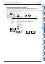
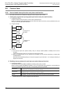
1. Input interrupt function (interrupt of external signal input (X))
By the input signal from an input (X000 to X005), the main sequence program is paused, and an interrupt routine
program is executed with priority.
The input interrupt execution timing can be specified on the rising edge or falling edge of the signal by the pointer
number.
→ For details, refer to Section 36.3.
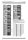
2. Input interrupt delay function (interrupt of external signal input (X))
By the input signal from an input (X000 to X005), the main sequence program is paused, and an interrupt routine
program is executed with priority after the delay time (set in units of 1 ms).
The input interrupt execution timing can be specified on the rising edge or falling edge of the signal by the pointer
number.
→ For details, refer to Section 36.4.
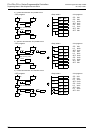
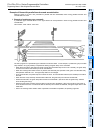
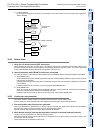
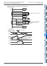
3. Timer interrupt function (timer interrupt activated in a constant cycle)
The main sequence program is paused in a constant cycle of 10 to 99 ms, and an interrupt routine program is
executed with priority.
→ For details, refer to Section 36.5.
4. High speed counter interrupt function (interrupt function given at counting up)
When the current value of a high speed counter reaches a specified value, the main sequence program is paused and
an interrupt routine program is executed with priority.
→ For details, refer to Section 36.6.
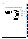
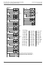
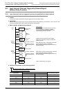
5. Pulse catch function
When the input signal from an input (X000 to X007) turns ON from OFF, a special auxiliary relay M8170 to M8177 is
set in the interrupt processing. By a relay M8170 to M8177 in a normal sequence program, a signal that remains ON
longer than the receivable range with regular input processing can be easily received.
When processing such a signal that turns ON and OFF several times in one operation cycle, however, use the input
interrupt function.
→ For details, refer to Section 36.7.
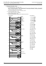
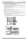
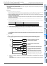
6. Pulse width/Pulse period measurement function
When the input signal from an input (X000, X001, X003 or X004) turns ON from OFF, the value of the 1/6 µs ring
counter at the input signal rising edge is stored in special data registers.
When the input signal turns OFF from ON, the value of the 1/6 µs ring counter at the input signal falling edge is stored
in special data registers. At the same time, the difference in the counter value between the rising edge and the falling
edge is divided by "60", and the pulse width in units of 10 µs is stored in special data registers.
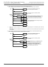
In the pulse period measurement mode, when the input signal turns ON from OFF, the difference between the
previous rising of the input signal and the current rising of the input signal is divided by "60", and then the pulse period
in units of 10 µs is stored in special data registers.
→ For details, refer to Section 36.8.