


468
FX3G/FX3U/FX3UC Series Programmable Controllers
Programming Manual - Basic & Applied Instruction Edition
16 External FX Device – FNC 80 to FNC 89
16.6 FNC 85 - VRRD / Volume Read
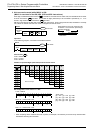
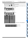
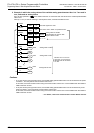
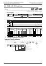
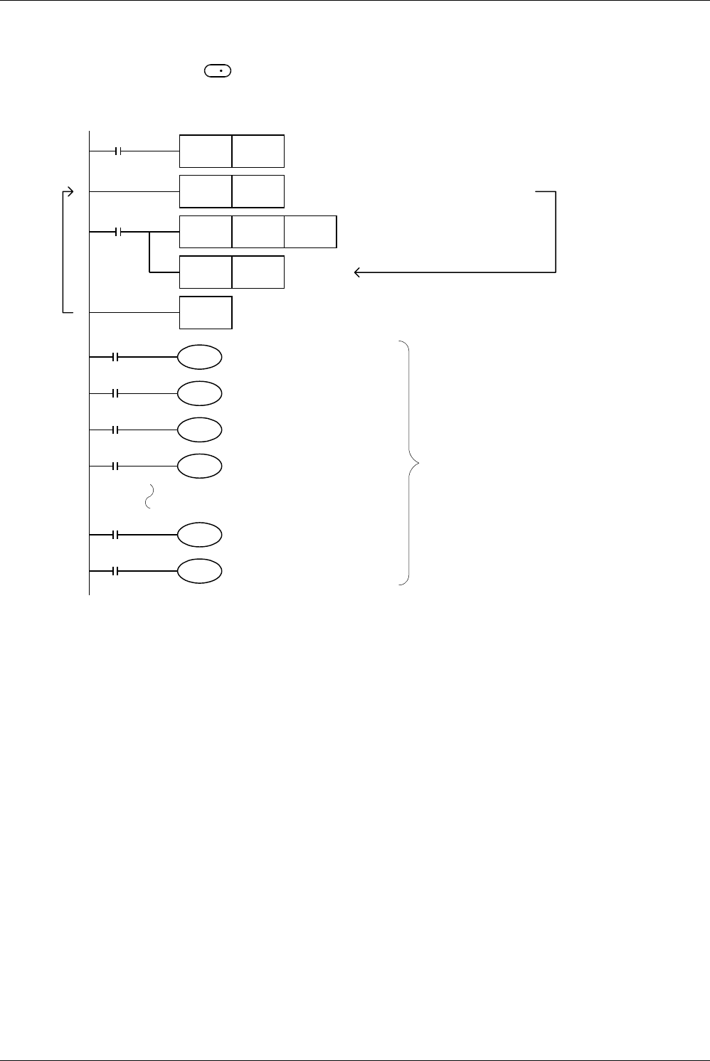
2. Example in which the analog values of the variable analog potentiometers Nos. 0 to 7 are read in
turn, and used as analog timers
K0 to K7 are specified in of the VRRD instruction in accordance with the values of the variable potentiometers
VR0 to VR7.
Index (Z = 0 to 7) is used for indexing in the sequence below, and K0Z indicates K0 to K7.
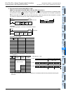
Cautions
• In 14-point and 24-point type FX3G PLCs, the variable analog potentiometer board can be connected to the option
connector 1, and occupies the communication channel ch1.
In this case, the communication function using the communication channel ch1 is not available when the VRRD or
VRSC instruction is used.
• In 40-point and 60-point type FX
3G PLCs, the variable analog potentiometer board can be connected only to the
option connector 2, and occupies the communication channel ch2.
In this case, the communication function using the communication channel ch2 is not available when the VRRD or
VRSC instruction is used.
→ For details, refer to the Communication Control Edition manual.
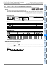
S
1
S
M8000
RST Z
FNC 08
FOR
K8
FNC 85
VRRD
K0Z D200Z
Z
M8000
FNC 24
INC
FNC 09
NEXT
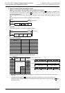
RUN
monitor
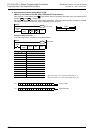
X000
T0
D200
T0
Y000
X001
T1
D201
T1
Y001
X007
T7
D207
T7
Y007
Because T0 to T7 are 100
ms timers, 0 to 25.5 sec are
obtained from the set values
0 to 255.
The index register Z is reset.
The routine "FOR ~ NEXT" is repeated 8 times.
Z + 1
→
Z
Analog values of variable
potentiometers are stored in data
registers D200 to D207.
0
4
7
16
17
21
23
27
59
63
Analog timer of VR0
Analog timer of VR1
Analog timer of VR7