


127
FX3G/FX3U/FX3UC Series Programmable Controllers
Programming Manual - Basic & Applied Instruction Edition
4 Devices in Detail
4.9 Data Register and File Register [D]
1
Introduction
2
Overview
3
Instruction
List
4
Devices
in Detail
5
Specified the
Device &
Constant
6
Before
Programming
7
Basic
Instruction
8
FNC00-FNC09
Program Flow
9
FNC10-FNC19
Move & Compare
10
FNC20-FNC29
Arith. & Logic
Operation
4.9.4 Functions and operation examples of file registers
A file register is a device for setting the initial value of a data register with the same number.
Each file register stores 16-bit data (whose most significant bit specifies the positive or negative sign). Two file
registers combined can store 32-bit numeric data (whose most significant bit specifies the positive or negative sign).
Up to 7000 data registers starting from D1000 can be specified as file registers by the parameter setting.
• In parameter settings, 1 to 14 blocks can be specified. One block secures 500 file registers, but uses the program
memory area by 500 steps.
• When some of data registers starting from D1000 are specified as file registers, the remaining data registers not
specified as file registers can be used as data registers.
This section explains how to handle file registers.
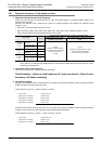
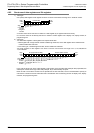
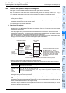
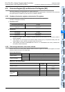
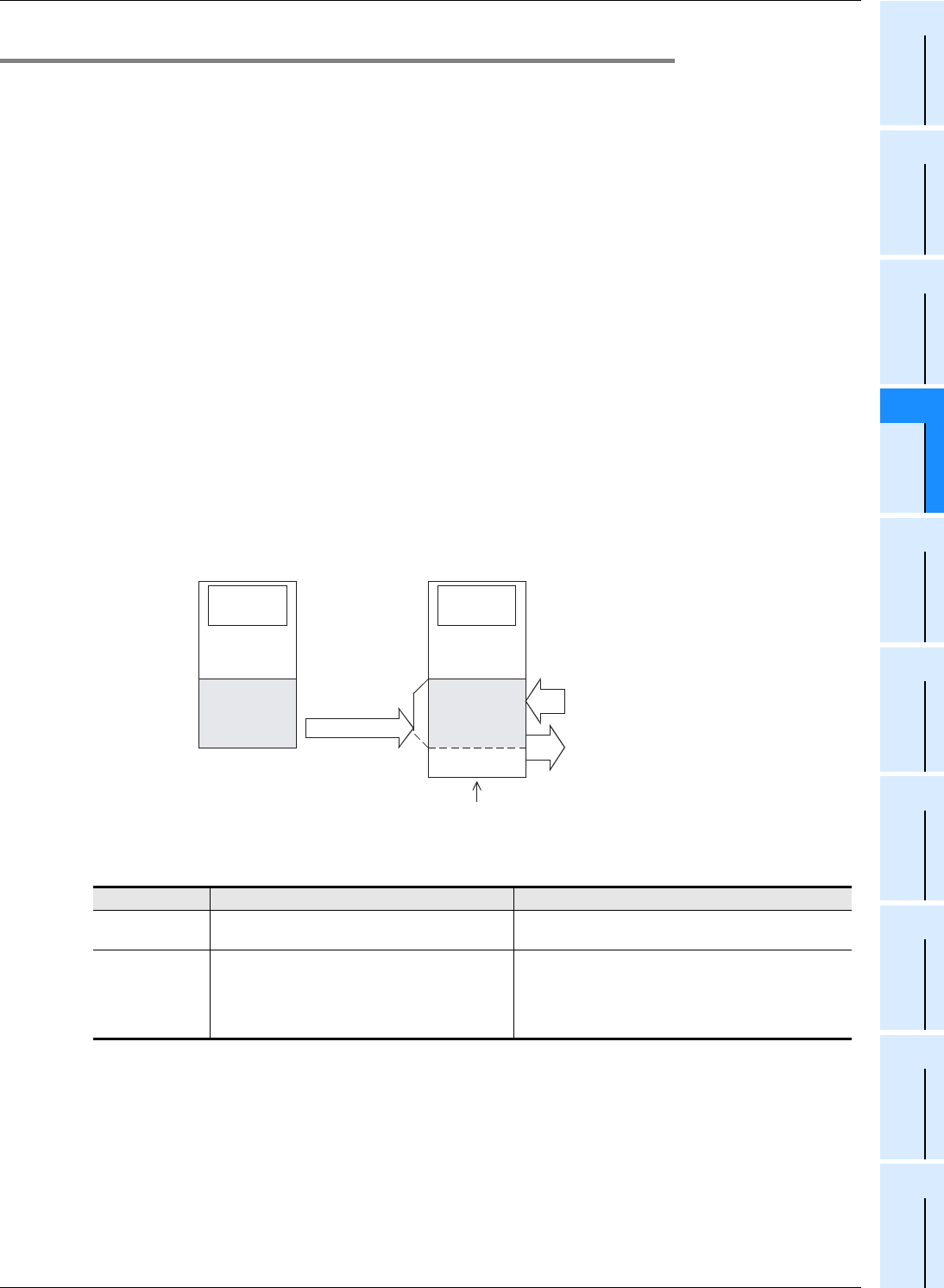
1. Operation of file registers
• The contents of the file register area [A] set inside the built-in memory or memory cassette are batch-transferred to
the data memory area [B] inside the system RAM when the power of the PLC is turned ON or when the PLC mode
switches from STOP to RUN.
When data registers are specified as file registers by the parameter setting, the contents of the file register area [A]
inside the program memory are transferred when the power of the PLC is turned ON or when the PLC mode
switches from STOP to RUN. This means that the contents changed in the data memory are initialized every time
when the PLC turns ON or when the PLC mode switches from STOP to RUN.
When it is necessary to save data changed in the data memory using a sequence program, update the file register
area [A] to the changed values by the same-number register update mode in BMOV
(FNC 15) instruction described later.
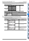
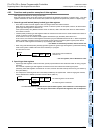
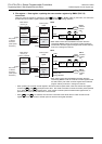
• Difference between BMOV (FNC 15) instruction and other instructions
The table below shows the differences between the BMOV (FNC 15) instruction and other applied instructions.
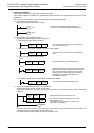
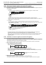
The data stored in data registers set as file registers are automatically copied from the file register area [A] to the
data register area [B] when restoring the power.
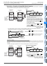
• When a file register is monitored from peripheral equipment, the data register area [B] inside the data memory is
read.
When "file register device current value change", "file register device forced reset" or "PLC memory all clear" is
executed from peripheral equipment, the file register area [A] inside the program memory is changed, and then the
data is automatically transferred to the data register area [B].
Accordingly, when file registers are to be overwritten, the program memory should be "built-in memory" or "memory
cassette whose protect switch is set to OFF". (The memory cassette cannot be overwritten from peripheral
equipment if its protect switch is set to ON.)
Instruction Transferred contents Remarks
BMOV instruction
Data can be read from and written to the file register
area [A] inside the program memory.
−
Applied
instructions other
than
BMOV
instruction
Data can be read from and written to the data
register area [B] inside the image memory in the
same way as general data registers.
Because the data register area [B] is provided inside the
system RAM in the PLC, its contents can be arbitrarily
changed without being limited by the optional memory
format.
Data register
[B]
Inside system
RAM
Inside built-in memory
or
memory cassette
Program
memory
Program/
comment
File register
[A]
D1000
500 points ×
14 blocks
maximum
(7000 points
maximum)
When power
is turned ON
When PLC
mode is
changed
from STOP
to RUN
Data
memory
Data register
Data register
D7999
D1000
D 0
Read
Write
The remaining area can be used as data registers for general purpose.
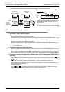
For devices D1000 and later specified
as operands in applied instructions othe
r
than BMOV (FNC 15) , indirectly
specified values for timers, counters or
devices in RST instructions can be read
from and written to the data register
area [B] in the same way as general
data registers.