


162
FX3G/FX3U/FX3UC Series Programmable Controllers
Programming Manual - Basic & Applied Instruction Edition
6 What to Understand before Programming
6.1 How to Read Explanation of Instructions
Outline
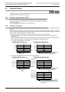
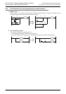
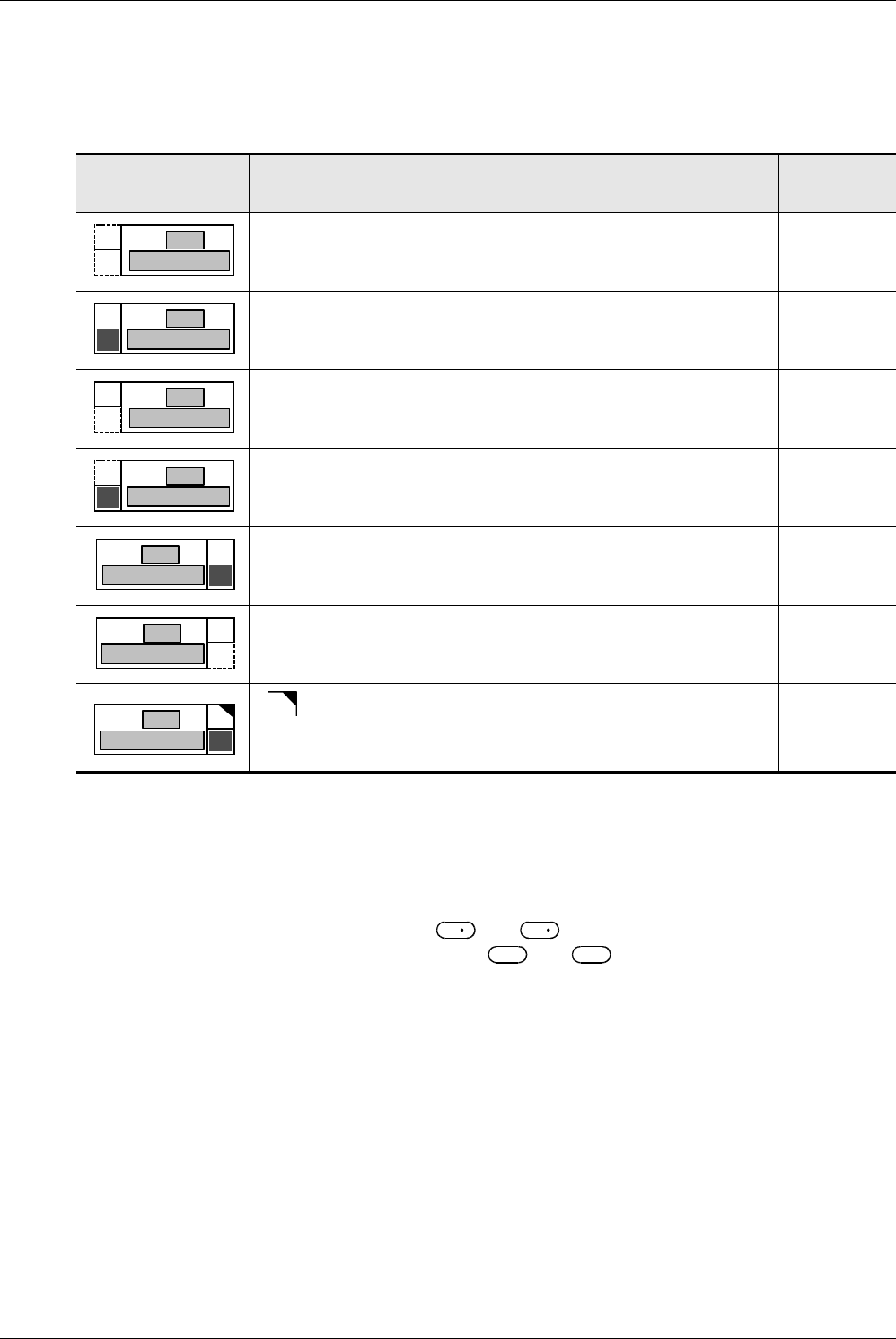
1. Instruction format
1) The applied instruction number (FNC No.) and instruction mnemonic are indicated. The table below shows the
meaning of simplified expression.
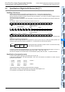
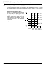
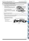
2. Set data
The contents of devices that can be specified as operands in instructions and available data types are described
below:
1) Contents
The contents of operands in each instruction are described below.
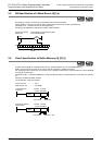
2) Indexing of the source and destination
In operands to which " " is added such as and , indexing is available.
Operands not allowing indexing are expressed as and .
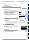
3) Data types
- Bit : Bit device
- 16-bit BIN : 16-bit binary code
- 32-bit BIN : 32-bit binary code
- 64-bit BIN : 64-bit binary code
- 16/32-bit BIN : 16-bit or 32-bit binary code
- 32/64-bit BIN : 32-bit or 64-bit binary code
- 4-digit BCD : 4-digit (16-bit) BCD code
- 8-digit BCD : 8-digit (32-bit) BCD code
- 4/8-digit BCD : 4-digit (16-bit) or 8-digit (32-bit) BCD code
- Character string : Character code such as ASCII code and shift JIS code
- Character string (only ASCII) : ASCII code
- Real number (binary) : Binary floating point
- Real number (decimal) : Scientific notation
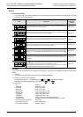
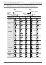
Mark Description
Applicable
instruction
(example)
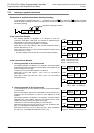
Dotted lines on the upper left and lower left sides indicate an independent instruction
not associated with the 16-bit or 32-bit type.
WDT(FNC 07)
Continuous lines on the upper left side indicates that 16-bit type is available. "D" on the
lower left side indicates that the 32-bit type is available.
MOV(FNC 12)
Dotted lines on the lower left side indicate that the 32-bit type does not exist.
Continuous lines on the upper left side indicate that only the 16-bit type is available.
CJ(FNC 00)
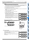
Dotted lines on the upper left side indicate that the 16-bit type does not exist. "D" on the
lower left side indicates that only the 32-bit type is available.
HSCS(FNC 53)
Continuous lines on the upper right side indicate that the continuous operation type is
available. "P" on the lower right side indicates that the pulse operation type is available.
CMP(FNC 10)
Dotted lines on the lower right side indicate that the pulse operation type does not exist.
Continuous line on the upper right side indicate that only the continuous operation type
is available.
MTR(FNC 52)
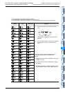
""on the upper right side indicates that the contents of the destination change in
every operation cycle when the continuous operation type is used.
When operation should be executed only during the driving of an instruction, use the
pulse operation type indicated by "P" on the lower right side.
INC(FNC 24)
P
FNC 12
MOV
No.
Instruction name
P
FNC 12
MOV
D
No.
Instruction name
P
FNC 12
MOV
No.
Instruction name
D
P
FNC 12
MOV
D
No.
Instruction name
D P
FNC 12
MOV
No.
Instruction name
PD
FNC 12
MOV
No.
Instruction name
D P
FNC 12
MOV
No.
Instruction name
S
S
1
S S
1