854
FX3G/FX3U/FX3UC Series Programmable Controllers
Programming Manual - Basic & Applied Instruction Edition
37 Operation of Special Devices (M8000 -, D8000 -)
37.2 Supplement of Special Devices (M8000 - and D8000 -)
37.2.4 Power failure detection time [D8008, M8008 and M8007]
1. FX3U PLC (AC power supply type)
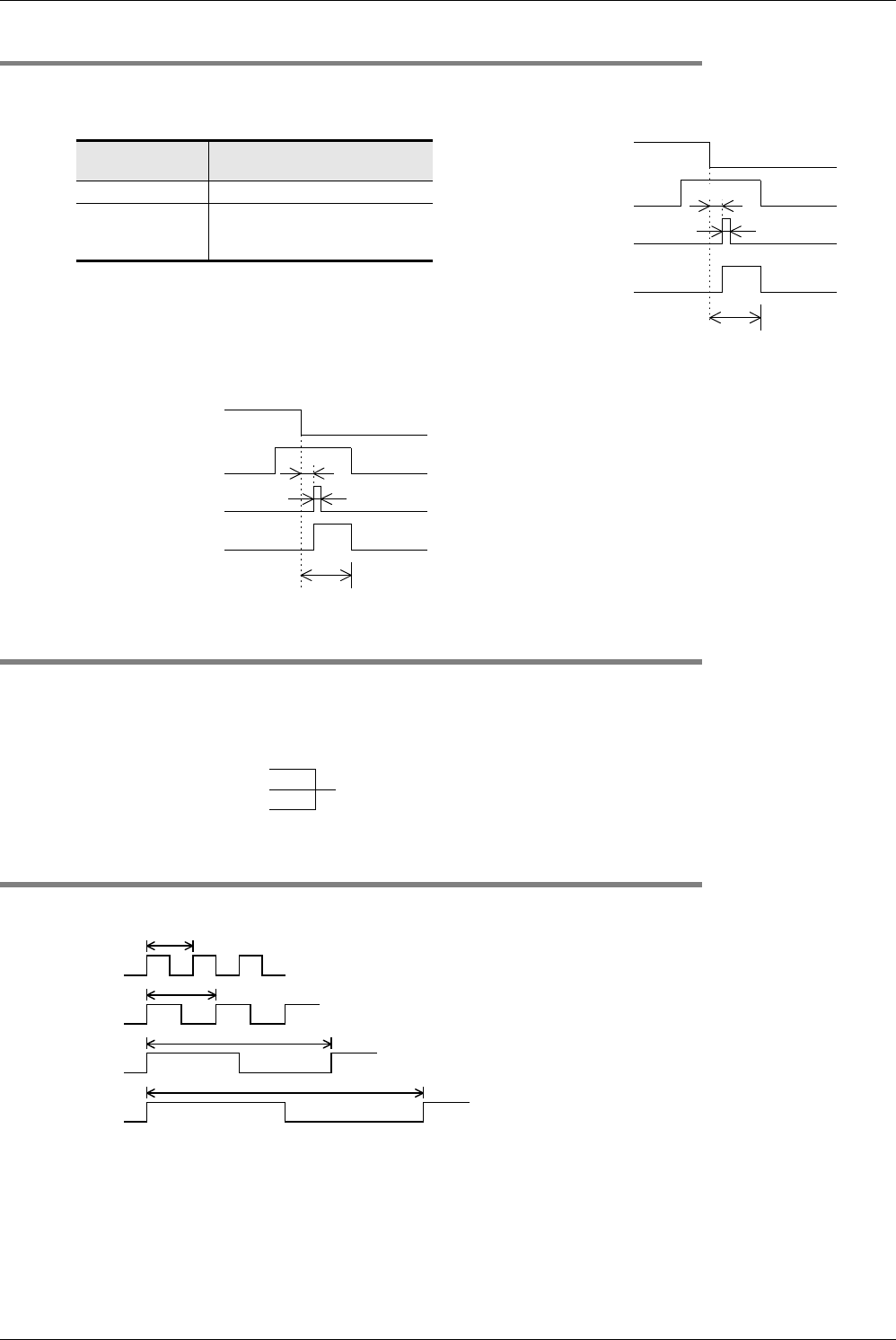
The table below shows the allowable momentary power failure time in FX3U PLCs (AC power supply type).
2. FX3U/FX3UC PLC (DC power supply type)
The allowable momentary power failure time in the FX3U/FX3UC PLCs (DC power supply type) is 5 ms. Do not
overwrite the power failure detection time in device D8008.
37.2.5 Scan time (monitor) [D8010 to D8012]
The present value, minimum value and maximum value of the PLC scan time (operation time) are stored in D8010,
D8011 and D8012 respectively (in 0.1-ms units).
When using the constant scan mode, the values stored in these devices include the waiting time for the constant scan
time.
37.2.6 Internal clock [M8011 to M8014]
The PLC has the following four types of internal clocks which are always oscillating while the PLC power is ON.
Supply voltage
Allowable momentary power
failure time
100V AC system 10 ms
200V AC system
Setting range: 10 to 100 ms
Set a value to D8008.
Default: 10 ms
1 scan time
Power failure
detection time
D8008
10ms
Approx. 5 ms
AC power supply
M8000: RUN monitor
M8007: Momentary
power failure
detection
M8008: Power failure
detected
1 scan time
Power failure detection time
D8008
5ms
Approx. 2 ms
DC power supply
M8000:RUN monitor
M8007:Momentary
power failure
detection
M8008:Power failure
detected
D8010: Present value
D8011: Minimum value
D8012: Maximum value
The values stored in these devices can be
monitored from peripheral equipment.
10ms
100Hz
100ms
10Hz
1s
1min
M8011
(10ms)
M8012
(100ms)
M8013
(1 sec)
M8014
(60 sec)
Caution:
Even while the PLC is in the STOP mode, these clocks are always
oscillating. Therefore, the rising edge of the RUN monitor (M8000)
does not synchronize with the clock start timing.
1Hz


