


31
FX3G/FX3U/FX3UC Series Programmable Controllers
Programming Manual - Basic & Applied Instruction Edition
2 Overview (Sequence Program)
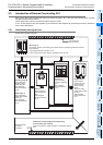
2.5 Introduction of Devices Constructing PLC
1
Introduction
2
Overview
3
Instruction
List
4
Devices
in Detail
5
Specified the
Device &
Constant
6
Before
Programming
7
Basic
Instruction
8
FNC00-FNC09
Program Flow
9
FNC10-FNC19
Move & Compare
10
FNC20-FNC29
Arith. & Logic
Operation
8. Index registers (V)(Z)
→ Refer to Section 4.11.
Among registers, there are index type registers V
and Z used for modification.
A data register V or Z is added to another device as
follows:
[In the case of "V0, Z0 = 5"]
D100V0 = D105, C20Z0 = C25 ← Device number +
V or Z value
Data registers and index registers are used for
indirectly specifying the set value of timers and
counters, or used in applied instructions.
9. Pointers (P)(I)
→ Refer to Section 4.12.
Pointers are classified into branch pointers and
interrupt pointers.
• A branch pointer (P) specifies the jump
destination of the conditional jump CJ (FNC 00) or
the call subroutine CALL (FNC 01) instruction.
• An interrupt pointer (I) specifies the routine of an
input interrupt, timer interrupt or counter interrupt.
10.Constants (K)(H)(E)
→ Refer to Chapter 5.
Constant numerical values used in the PLC, "K"
indicates a decimal integer value, "H" indicates a
hexadecimal value, and "E" indicates a real number
(floating point data).
Constants are used as set values or present values
of timers and counters, or operands for applied
instructions.