


203
FX3G/FX3U/FX3UC Series Programmable Controllers
Programming Manual - Basic & Applied Instruction Edition
7 Basic Instruction
7.9 MC, MCR
1
Introduction
2
Overview
3
Instruction
List
4
Devices
in Detail
5
Specified the
Device &
Constant
6
Before
Programming
7
Basic
Instruction
8
FNC00-FNC09
Program Flow
9
FNC10-FNC19
Move & Compare
10
FNC20-FNC29
Arith. & Logic
Operation
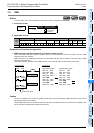
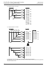
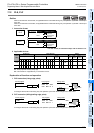
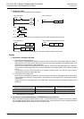
2) When the nesting structure is adopted
When using MC instructions inside MC instruction, increase the nest level "N" in turn in the way "N0 → N1 → N2
→ N3 → N4 → N5 → N6 → N7".
For returning from the nesting structure, reset the nest levels from the highest one in turn using MCR instruction in
the way "N7 → N6 → N5 → N4 → N3 → N2 → N1 → N0".
For example, if "MCR N5" is programmed without programming "MCR N6" and "MCR N7", the nest level is
returned to 5 at one time.
Available nest levels are from N0 to N7 (eight layers).
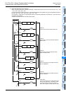
[B]
[A]
[C]
[B]
While X000
is OFF
[A]
N 1
N 2
X000
MC N 0 M100
N 0 M100
X001
Y000
X002
MC N 1 M101
N 1 M101
X003
Y001
X004
MC N 2 M102
N 2 M102
X005
Y002
MCR N 2
X006
Y003
MCR N 1
X007
Y004
MCR N 0
X010
Y005
N 0
N 1
N 2
N 0
[D]
[C]
While
X002 is
OFF
While
X004
is OFF
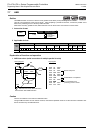
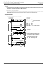
Circuit program
Level N0
The bus line B is active while X000 is ON.
Level N1
The bus line C is active while both X000 and
X002 are ON.
Level N2
The bus line D is active while all of X000,
X002 and X004 are ON.
Level N1
The bus line returns to the status of the bus
line C by "MCR N2".
Level N0
The bus line returns to the status of the bus
line B by "MCR N1".
Initial status
The bus line returns to the initial status of the
bus line A by "MCR N0". Accordingly, Y005
turns ON or OFF by turning ON or OFF of
X010 without regard to X000, X002 and X004.