182
FX3G/FX3U/FX3UC Series Programmable Controllers
Programming Manual - Basic & Applied Instruction Edition
7 Basic Instruction
7.2 OUT
3. Indexing
*1
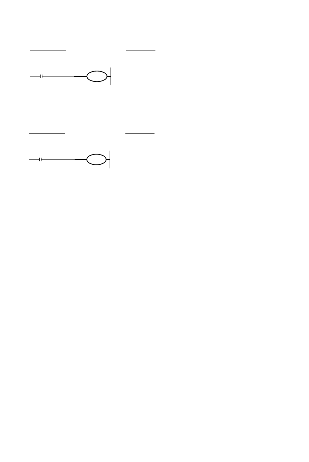
Devices used in OUT instruction can be indexed with index registers (V and Z).
(State relays (S), special auxiliary relays (M), 32-bit counters (C), and "D.b" cannot be indexed.)
The index registers V0 to V7 and Z0 to Z7 are
available for indexing.
When a used device is an input (X) or output (Y),
the value of an index register (V or Z) is
converted into an octal number, and then added.
Example: When the value of Z0 is "20", Y024
turns ON or OFF.
*1. This function is supported only in FX
3U
/FX3UC PLCs.
4. Bit specification of data register (D)
*1
A bit in data register (D) can be specified as a device used in OUT instruction.
When specifying a bit in data register, input "."
after a data register (D) number, and then input a
bit number (0 to F) consecutively.
Only 16-bit data registers are available.
Specify a bit number as "0, 1, 2, ... 9, A, B, ... F"
from the least significant bit.
Example: In the example shown on the left, the
bit 3 of D0 turns ON or OFF when X000
turns ON or OFF.
*1. This function is supported only in FX
3U
/FX3UC PLCs.
Caution
• When a special internal relay (M), timer or counter is used, program steps increase as described in "Setting range
of timers and counters" on the previous page.
• Do not use the last bit number of a data register (D) or extension register (R) as the set value of a 32-bit counter.
Errors
• When an I/O number used in OUT instruction does not exist due to indexing, M8316 (Non-existing I/O specification
error) turns ON.
• When the device number of a device (M, T or C) other than I/O used in OUT instruction does not exist due to
indexing, an operation error (error code: 6706) occurs.
Y000Z0
Circuit program List program
LD
OUT
0000
0001
X000
Y000Z0
X000
X000
D0.3
Circuit program List program
LD
OUT
0000
0001
X000
D0.3


