


807
FX3G/FX3U/FX3UC Series Programmable Controllers
Programming Manual - Basic & Applied Instruction Edition
36 Interrupt Function and Pulse Catch Function
36.3 Input Interrupt (Interrupt Triggered by External Signal) [Without Delay Function]
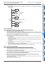
31
FNC275-FNC279
Data
Transfer 3
32
FNC280-FNC289
High Speed
Processing 2
33
FNC290-FNC299
Extension File
Register
34
FNC300-FNC305
FX
3U
-CF-ADP
35
SFC•STL
Programming
36
Interrupt
Function
37
Special Device
38
Error Code
A
Version Up
Information
B
Execution Times
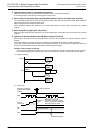
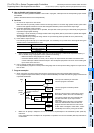
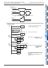
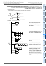
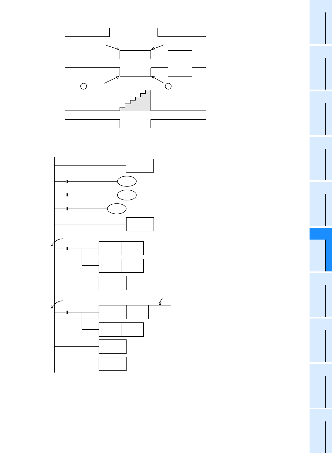
2. Example of program to measure the short pulse width using a high speed ring counter (only in
FX
3U/FX3UC PLCs)
Current
value of T246
1
2
6
X010: Preparation
for measurement
SW(X000,X001)
RST
T246
3
4
5
M0
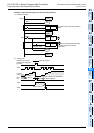
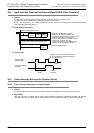
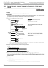
-Timing chart
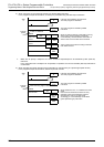
Part B in the previous page
I001(Interrupt processing) I100(Interrupt processing)
Part A in the previous page
Step
0
I001
Interrupt
pointer
X010
I100
Interrupt
pointer
X010
X010
Measurement data
When the rising edge of
X000 is detected
When the falling edge of
X001 is detected
D8099 is set to ON
Measurement
is completed
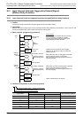
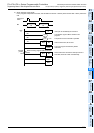
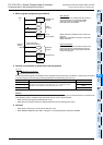
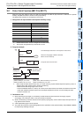
FNC 04
EI
M8099
FNC 06
FEND
FNC 03
IRET
FNC 12
M0V
FNC 03
IRET
END
RST D8099
RST M0
D8099 D0
SET M0
When X001 turns OFF: The ring counter value
is transferred to D0,
and measurement is
completed.
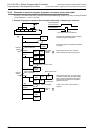
Interrupts are enabled by the EI instruction.
The main program is described.
The ring counter is set to ON.
When X000 turns ON: The ring counter is reset
to OFF, and
measurement is started.
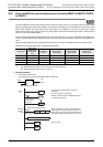
The special data register M8099 up-counts the
0.1 ms clock from the next operation cycle after
being driven.
When the count value exceeds "32767", it is
returned to "0".