


187
FX3G/FX3U/FX3UC Series Programmable Controllers
Programming Manual - Basic & Applied Instruction Edition
7 Basic Instruction
7.4 OR, ORI
1
Introduction
2
Overview
3
Instruction
List
4
Devices
in Detail
5
Specified the
Device &
Constant
6
Before
Programming
7
Basic
Instruction
8
FNC00-FNC09
Program Flow
9
FNC10-FNC19
Move & Compare
10
FNC20-FNC29
Arith. & Logic
Operation
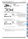
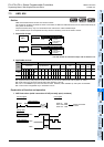
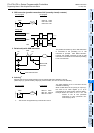
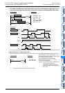
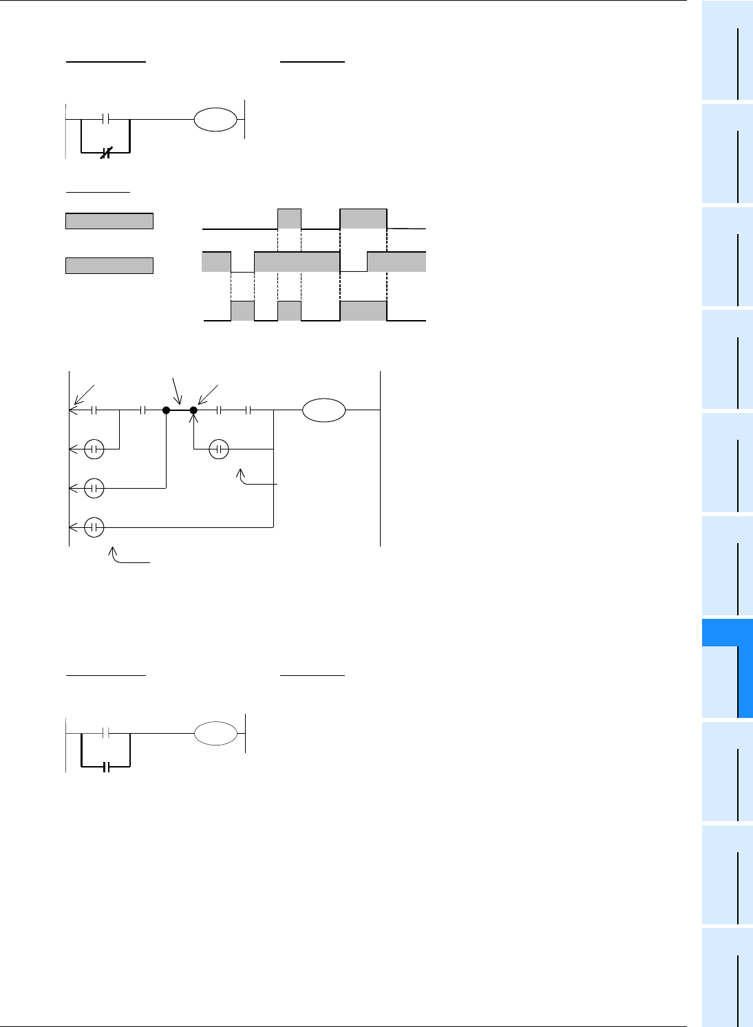
2. ORI instruction (parallel connection of NC (normally closed) contacts)
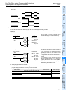
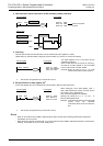
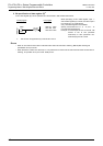
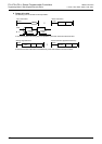
3. Relationship with ANB instruction
The parallel connection by OR or ORI instruction
is connected to the preceding LD or LDI
instruction in principle. After ANB instruction,
however, the parallel connection by OR or ORI
instruction is connected to the second preceding
LD or LDI instruction.
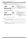
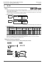
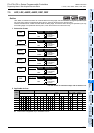
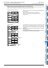
4. Indexing
*1
Devices used in OR and ORI instruction can be indexed with index registers (V and Z).
(State relays (S), special auxiliary relays (M), 32-bit counters, and "D.b" cannot be indexed.)
The index registers V0 to V7 and Z0 to Z7 are
available for indexing.
When a used device is an input (X) or output (Y),
the value of an index register (V or Z) is
converted into an octal number, and then added.
Example: When the value of V0 is "10", OR
contact is set to ON (becomes
conductive) or OFF (becomes non-
conductive) by X013.
*1. This function is supported only in FX
3U
/FX3UC PLCs.
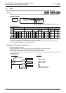
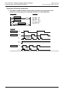
Timing chart
ORI instruction
LD instruction
X000
Y001
X002
Circuit program
List program
LD
ORI
OUT
0000
0001
0002
X000
X002
Y001
Y001
X002
X000
ON ON
ON ON
ONONON
ON
OR
OR
OR
OR
LD
LD
ANB
Before ANB
instruction
After ANB instruction
Circuit program List program
LD
OR
OUT
0000
0001
0004
X000
X001V0
Y000
Y000
X001V0
X000