180
FX3G/FX3U/FX3UC Series Programmable Controllers
Programming Manual - Basic & Applied Instruction Edition
7 Basic Instruction
7.2 OUT
7.2 OUT
Outline
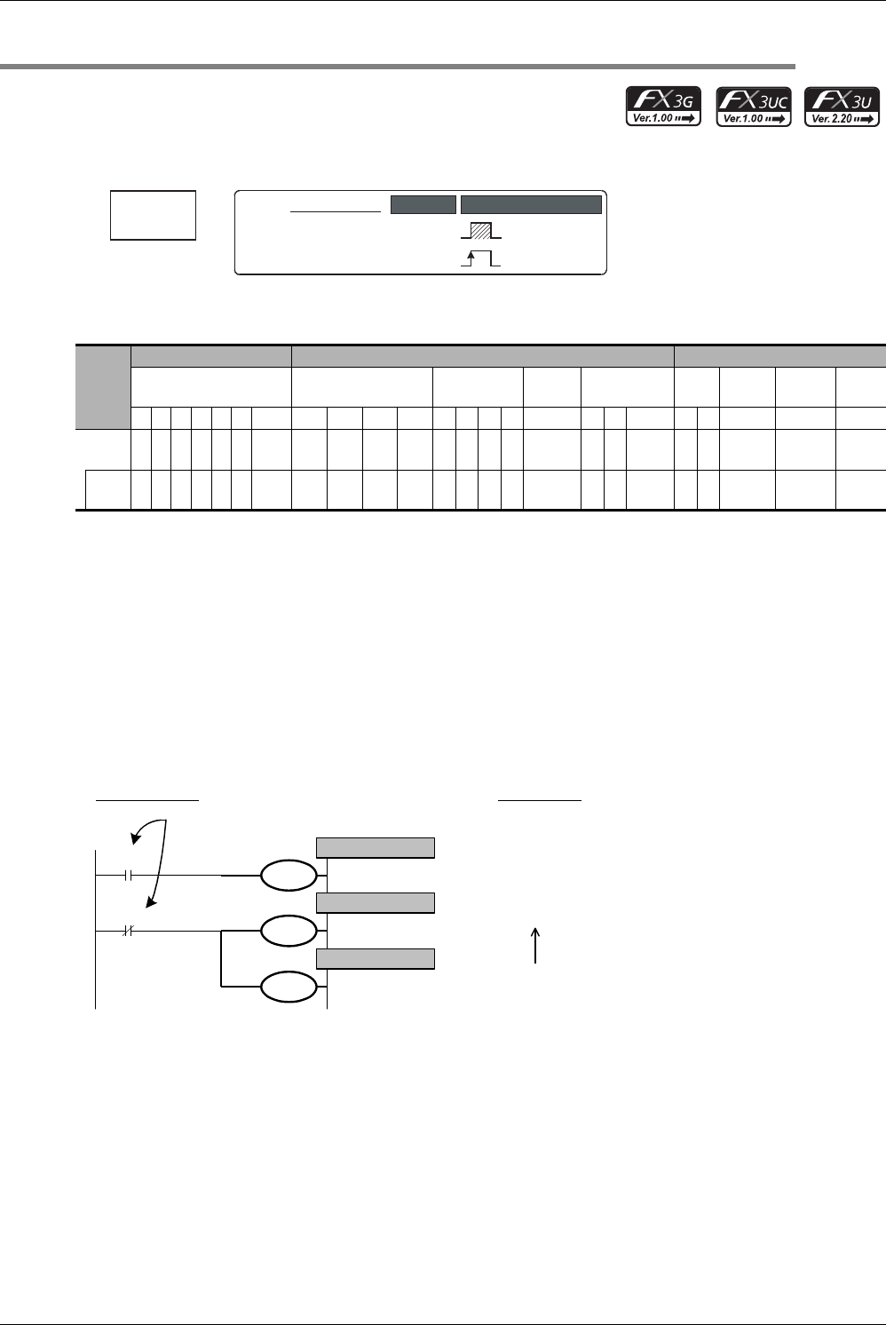
OUT instruction drives coils of output relays (Y), auxiliary relays (M), state relays (S), timers (T) and counters (C).
1. Instruction format
→ For the number of instruction steps, refer to Section 7.15.
2. Applicable devices
S1: Special auxiliary relays (M) and 32-bit counters (C) cannot be indexed with index registers (V and Z).
S2: State relays (S) cannot be indexed with index registers (V and Z).
S3: "D.b" is available only in FX
3U and FX3UC PLCs. However, index modifiers (V and Z) are not available.
S4: This function is supported only in FX
3U/FX3UC PLCs.
Explanation of function and operation
1. When a bit device is used
A device described in OUT instruction turns ON or OFF according to the driven contact status.
Parallel OUT instructions can be used consecutively as many times as necessary.
In the program example shown below, OUT M100 and OUT M101 are parallel.
If two or more OUT instructions are executed for a same device number, however, the double output (double coil)
operation is resulted.
Instruc-
tion
Bit Devices Word Devices Others
System User Digit Specification System User
Special
Unit
Index
Con-
stant
Real
Number
Charac-
ter String
Pointer
XYMTCSD.b KnX KnY KnM KnS T C D R U\G VZModifyKH E ""P
OUT 3
S
1
3
S
1
S
2
S3 S4
Set
value
33
S
4
3
OUT
OUT
Basic Instruction
OUT
−
Continuous
Operation
Pulse (Single)
Operation
Mnemonic Operation Condition
Program step numbers are
automatically controlled.
Circuit program
List program
LD
OUT
LDI
OUT
OUT
0000
0001
0002
0003
0004
X000
Y000
X001
M100
M101
X000
Y000
X001
M100
M101
OUT instruction
OUT instruction
OUT instruction
Drive contact of
OUT instruction


