


755
FX3G/FX3U/FX3UC Series Programmable Controllers
Programming Manual - Basic & Applied Instruction Edition
35 SFC Program and Step Ladder
35.1 SFC Program
31
FNC275-FNC279
Data
Transfer 3
32
FNC280-FNC289
High Speed
Processing 2
33
FNC290-FNC299
Extension File
Register
34
FNC300-FNC305
FX
3U
-CF-ADP
35
SFC•STL
Programming
36
Interrupt
Function
37
Special Device
38
Error Code
A
Version Up
Information
B
Execution Times
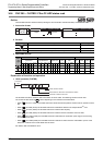
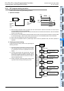
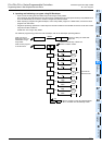
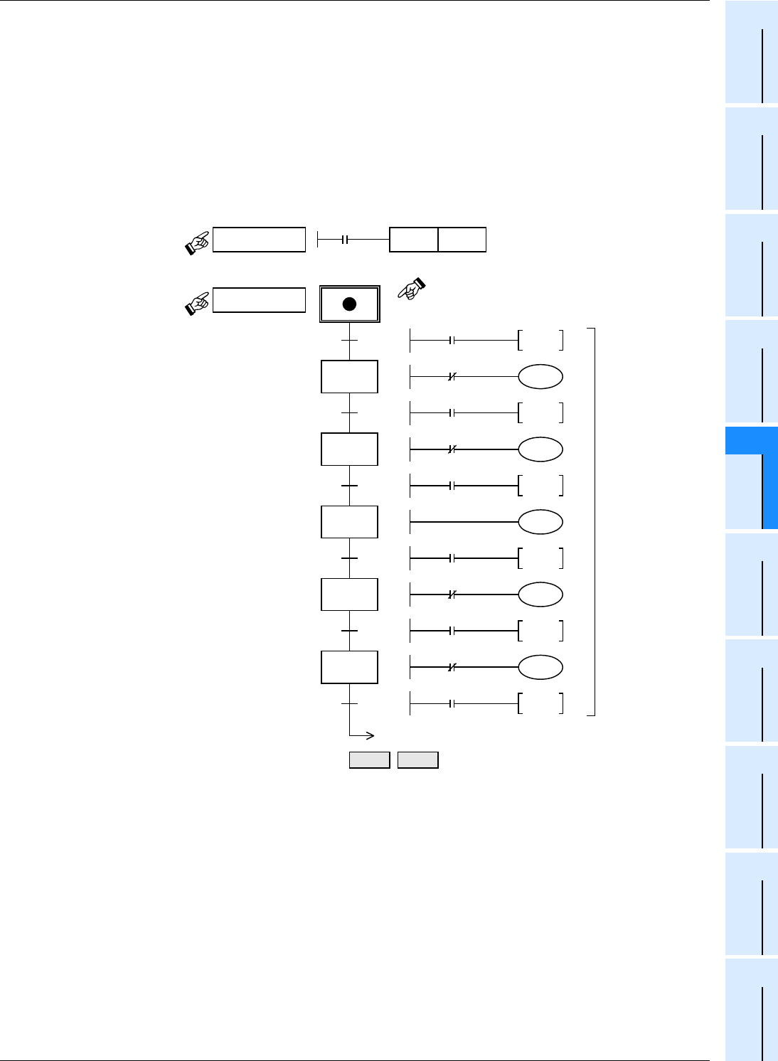
4. Inputting and indicating a program using GX Developer
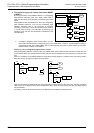
• Input a circuit for setting the initial state relay to ON using the relay ladder.
In this example, the initial state relay S0 is set to ON in a ladder block using the special auxiliary relay M8002 which
turns ON momentarily when the PLC mode is changed from STOP to RUN.
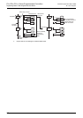
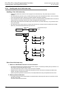
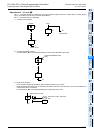
• When inputting a program using GX Developer, write a relay ladder program to a ladder block, and write an SFC
program to an SFC block.
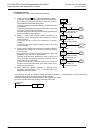
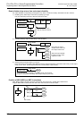
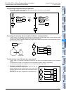
• Programs expressing operations in state relays and transfer conditions are handled as internal circuits of the state
relays and transfer conditions.
Create each one using a relay ladder.
For details of programming procedure in GX Developer, refer to GX Developer Operating Manual.
Y023
Y021
Write a circuit not
belonging to SFC to a
ladder block using a
relay ladder.
Write an SFC program
to an SFC block.
Ladder block
SFC block
M8002
SET S0
Program for setting the initial state
relay to ON
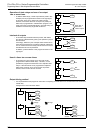
Indicate the state relay number and
transfer condition number.
0
20
0
1
21
2
22
3
23
4
24
5
S0
RET END
X000
TRAN
Y021
Y023
X001
TRAN
T0
X002
TRAN
Y023
Y021
T0
TRAN
Y021
Y023
X003
TRAN
X002
TRAN
When a program is input using GX Developer,
“RET” and “END” are automatically written.
K50
Input them as
internal circuits.