


98
FX3G/FX3U/FX3UC Series Programmable Controllers
Programming Manual - Basic & Applied Instruction Edition
4 Devices in Detail
4.6 Counter [C]
4.6.4 Functions and operation examples
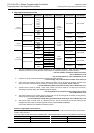
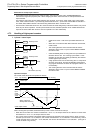
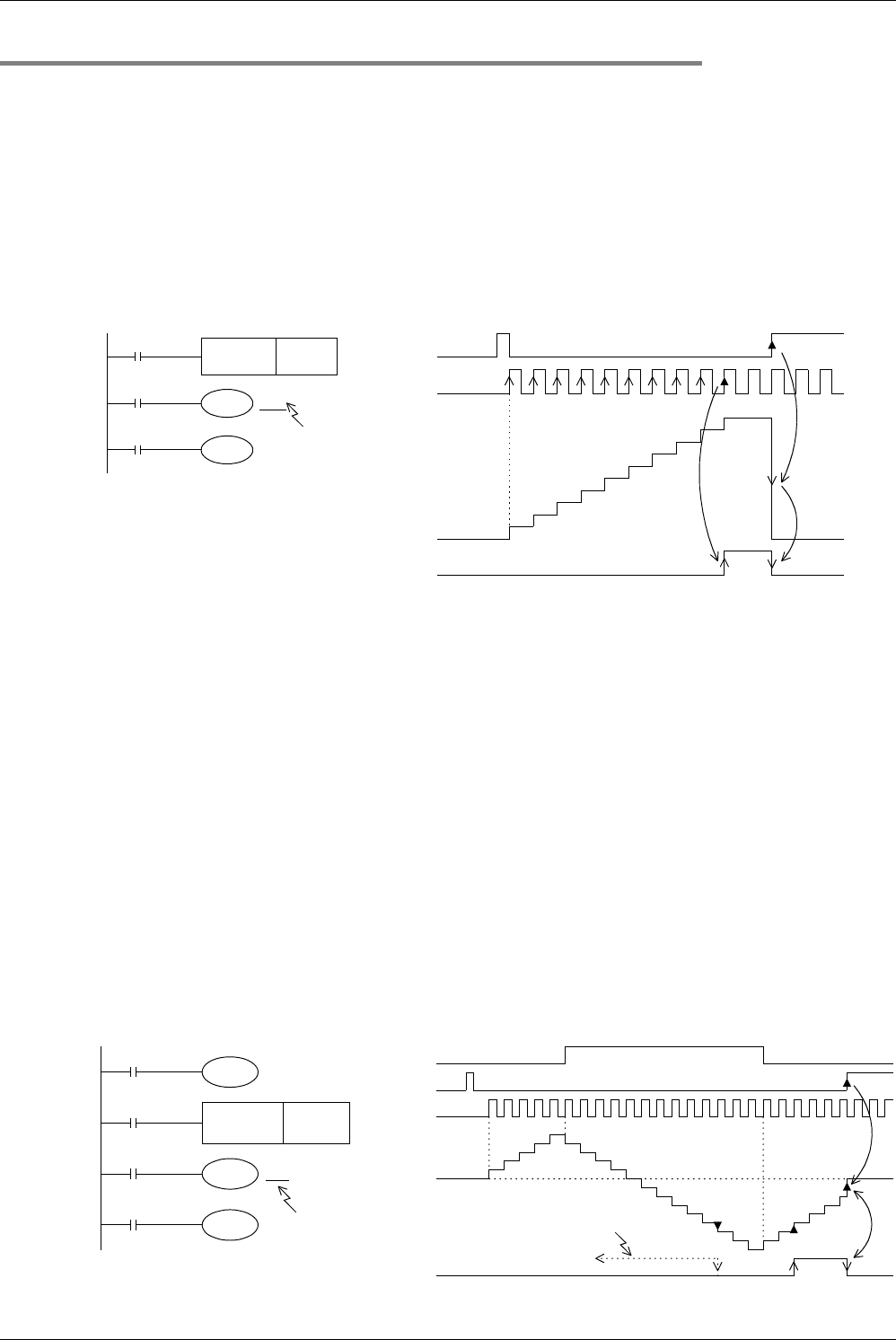
1. General type and latched (battery backed) type 16-bit up counters
• The valid set range of 16-bit binary up counter is from K1 to K32767 (decimal constant).
K0 provides the same operation as K1, and the output contact turns on at the first counting.
• In general type counters, the counter value is cleared when the PLC turns off. In latch type counters, however, the
counter value just before power failure is stored (backed up by the battery); The counter value in the subsequent
operations can be added to the last counter value.
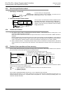
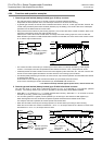
• Every time the coil C0 is driven by the counting input X011, the current value of the counter increases. When a coil
instruction is executed 10 times, the output contact turns on.
After that, the current value of the counter does not change even if the counting input X011 turns on after that.
When the RST input X010 turns ON and then RST instruction is executed, the current value of the counter is reset
to "0" and the output contact returns.
• The counter set value can be set by a constant (K) as shown above, or indirectly specified by a data register
number. For example, when D10 is specified and the contents of D10 are "123", it is equivalent to "K123".
• If data beyond the set value is written to the current value register by MOV instruction, etc., the OUT coil turns ON
and the current value register becomes the set value when the next counting input is received.
• For latched (battery backed) type counters, the current value, output contact operation and reset status are backed
up against power failure.
In FX
3U/FX3UC PLCs, latched type counters are backed up by the battery built into the PLC.
In FX
3G PLCs, latched type counters are backed up by the EEPROM built into the PLC.
→ For details on backup methods against power failure, refer to Section 2.6.
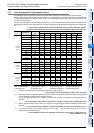
2. General type and latched (battery backed) type 32-bit bi-directional counters
The valid set range of 32-bit binary bi-directional counters is from −2,147,483,648 to +2,147,483,647 (decimal
constant). The counting direction (up or down) is specified by special auxiliary relays M8200 to M8234.
• When M8UUU is driven for CUUU, a counter executes down-counting. When M8UUU is not driven, a counter
executes up-counting. (Refer to the previous page.)
• The set value (positive or negative) can be specified by a constant (K) or the contents of data registers (D).
When data registers are used, 32-bit data composed of paired serial devices are treated as set values.
For example, when D0 is specified, D1 and D0 provide a 32-bit set value.
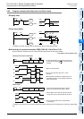
• When the coil C200 is driven by the counting input X014, a counter starts up-counting or down-counting.
When the current value of a counter increases from "−6" to "−5", the output contact is set. When the current value
decreases from "−5" to "−6", the output contact is reset.
X010
RST C 0
X011
C 0
C 0
Y000
K10
Set value (constant)
It can be specified
indirectly also.
0
1
2
3
4
5
6
7
8
9
10
X010
X011
Current
value
Y000
X013
RST C200
X014
C200
C200
Y001
K-5
Set value (constant)
It can be specified
indirectly also.
X012
M8200
X012
X013
X014
Current
value
Y001
Up counting
Down counting
Up counting
0
1
2
3
4
5
4
3
2
1
0
−
1
−
2
−
3
−
4
−
5
−
6
−
7
−
8
When output has
been already
activated.
−
7
−
6
−
5
−
4
−
3
0