


758
FX3G/FX3U/FX3UC Series Programmable Controllers
Programming Manual - Basic & Applied Instruction Edition
35 SFC Program and Step Ladder
35.1 SFC Program
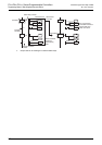
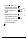
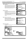
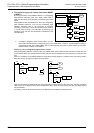
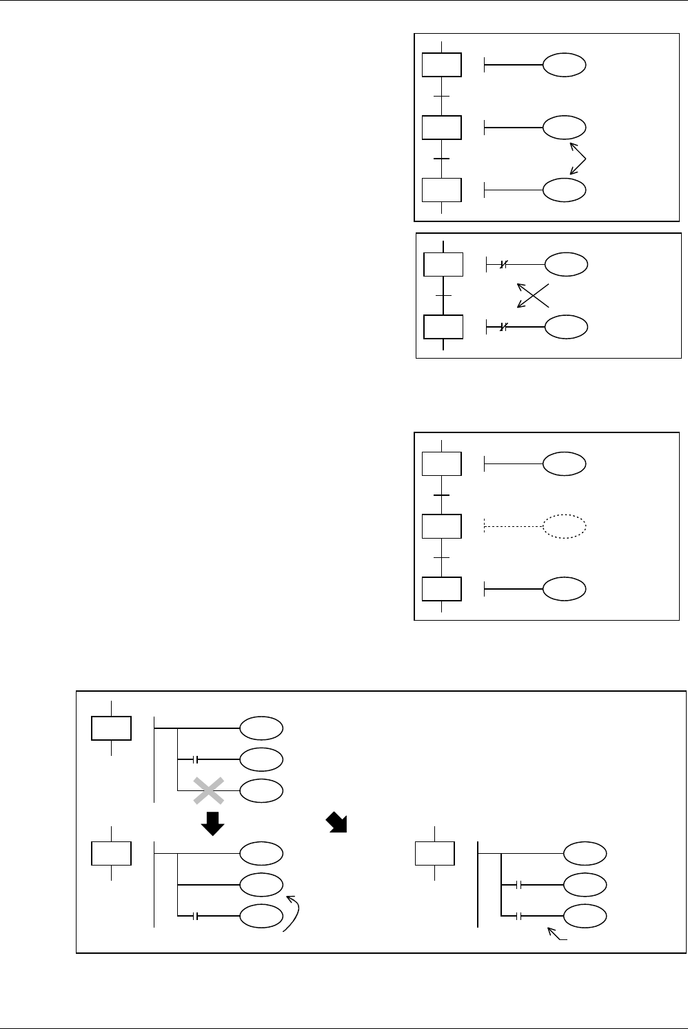
Operation of state relays and use of an output
two or more times
• In different state relays, a same output device (Y002 in this
example) can be programmed as shown in the right figure.
In this case, when S21 or S22 is ON, Y002 is output.
However, if the same device as an output coil (Y002) in a
state relay is programmed in a ladder block program or if a
same output coil is programmed twice in one state relay, it is
handled in the same way as general double coil.
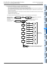
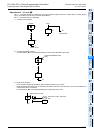
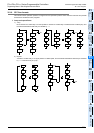
Interlock of outputs
• In the state relay ON status transfer process, both states
turn ON only instantaneously (during one operation cycle) at
the same time.
Accordingly, between a pair of outputs which should not be
set to ON at the same time, provide an interlock outside the
PLC in conformance to the handy manual of the PLC so that
simultaneous ON can be prevented.
In addition, provide interlock in the program as shown in the
right figure.
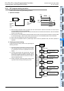
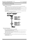
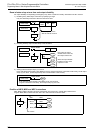
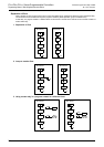
Use of a timer two or more times
• In the same way as an output coil, a timer coil can be
programmed in different state relays. However, it is not
permitted to program the same timer coil in adjacent state
relays. If the same timer coil is programmed in adjacent
state relays, the timer coil is not set to OFF at process
transfer, so the current value is not reset.
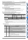
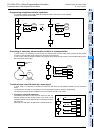
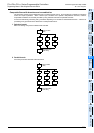
Output driving method
• It is not permitted to write program an instruction not requiring a contact after LD or LDI instruction from a bus line in
a state relay.
Change such a circuit as shown below.
21
22
20
Y001
Y002
Y002
When S21 or
S22 is ON,
Y002 is output.
21
20
Y001
Y002
Y001
Y002
Forward
rotation
Backward rotation
41
42
40
T1
T1
T1
K10
K20
Not
allowed
10
Y001
X005
Y002
Y003
10
Y001
X005
Y002
Y003
Move the
position.
10
Y001
M8000
Y003
Y002
Insert "Always ON"
contact.
X005
RUN
monitor
or
Change
Change