451
FX3G/FX3U/FX3UC Series Programmable Controllers
Programming Manual - Basic & Applied Instruction Edition
15 External FX I/O Device – FNC 70 to FNC 79
15.10 FNC 79 – TO / Write To A Special Function Block
11
FNC30-FNC39
Rotation and
Shift
12
FNC40-FNC49
Data Operation
13
FNC50-FNC59
High Speed
Processing
14
FMC60-FNC69
Handy
Instruction
15
FNC70-FNC79
External FX I/O
Device
16
FNC80-FNC89
External FX
Device
17
FNC100-FNC109
Data
Transfer 2
18
FNC110-FNC139
Floating Point
19
FNC140-FNC149
Data
Operation 2
20
FNC150-FNC159
Positioning
Control
15.10 FNC 79 – TO / Write To A Special Function Block
Outline
This instruction writes data from a PLC to buffer memories (BFM) in a special extension unit/block.
When a large capacity of data is written to buffer memories (BFM) by this instruction, a watchdog timer error may
occur. When splitting the data to be written does not affect the control, use WBFM (FNC279) instruction.
→ For WBFM (FNC279) instruction, refer to Section 31.2.
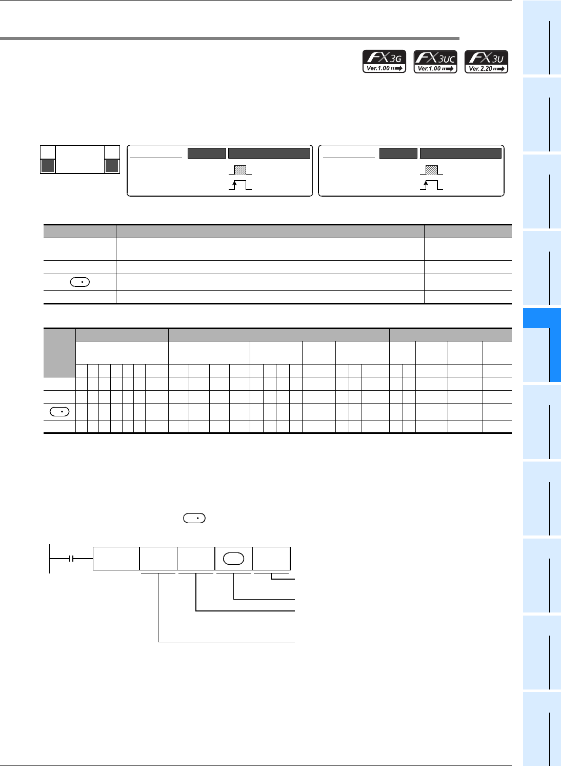
1. Instruction format
2. Set data
3. Applicable devices
Explanation of function and operation
1. 16-bit operation (TO and TOP)
→ For the common items between FROM instruction and TO instruction, refer to Subsection 15.9.1.
PLC (word device) → Special extension unit/block (BFM)
"n"-point 16-bit data starting from inside a PLC are transferred (written) to "n"-point buffer memories starting
from the buffer memory (BFM) # m2 inside a special extension unit/block No. m1.
Operand Type Description Data Type
m1
Unit number of a special extension unit/block
(K0 to K7 from the right side of the main unit)
16- or 32-bit binary
m2 Transfer destination buffer memory (BFM) number 16- or 32-bit binary
Device number storing the transfer source data 16- or 32-bit binary
n Number of transfer points 16- or 32-bit binary
Oper-
and
Type
Bit Devices Word Devices Others
System User Digit Specification System User
Special
Unit
Index
Con-
stant
Real
Number
Charac-
ter String
Pointer
XYMTCSD
.b KnX KnY KnM KnS T C D R
U\G
V Z Modify K H E "
"P
m1 33 33
m2 33 33
3333333 333
n 33 33
P
FNC 79
TO
D
DTO
DTOP
Mnemonic Operation Condition
32-bit Instruction
17 steps
Continuous
Operation
Pulse (Single)
Operation
16-bit Instruction
9 steps
Mnemonic Operation Condition
Continuous
Operation
Pulse (Single)
Operation
TO
TOP
S
S
S
Command
input
FNC 79
TO
m1 m2 nS
Unit No.
m1 = 0 to 7
Transfer destination (Special
extension unit/block) BFM #
m2 = 0 to 32766
Transfer source (PLC)
Number of transfer points
n = 1 to 32767


