


413
FX3G/FX3U/FX3UC Series Programmable Controllers
Programming Manual - Basic & Applied Instruction Edition
14 Handy Instruction – FNC 60 to FNC 69
14.9 FNC 68 – ROTC / Rotary Table Control
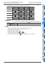
11
FNC30-FNC39
Rotation and
Shift
12
FNC40-FNC49
Data Operation
13
FNC50-FNC59
High Speed
Processing
14
FMC60-FNC69
Handy
Instruction
15
FNC70-FNC79
External FX I/O
Device
16
FNC80-FNC89
External FX
Device
17
FNC100-FNC109
Data
Transfer 2
18
FNC110-FNC139
Floating Point
19
FNC140-FNC149
Data
Operation 2
20
FNC150-FNC159
Positioning
Control
Explanation of function and operation
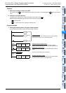
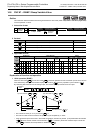
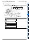
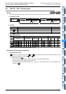
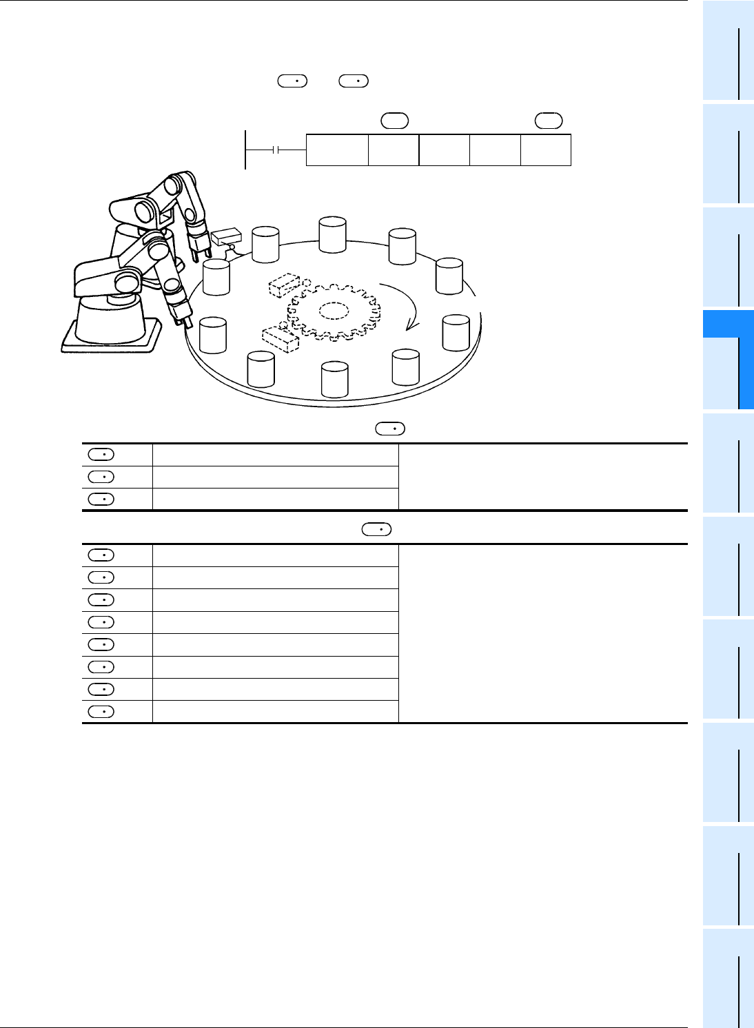
1. 16-bit operation (ROTC)
The table rotation is controlled by "m2", and so that a product can be efficiently put into or taken out of
the rotary table divided into "m1" (=10) sections as shown in the figure below.
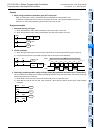
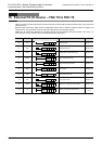
1) Register (word device) specifying the calling condition
2) Register (bit device) specifying the calling condition
Works as a register for counting.
Set them in advance using a transfer instruction.
+ 1
Sets the port No. to be called.
+ 2
Sets the product No. to be called.
:
A phase signal
Construct an internal contact circuit in advance which is driven
by the input signal (X)
+ 1
B phase signal
+ 2
Zero point detection signal
+ 3
Forward rotation at high speed
+ 4
Forward rotation at low speed
+ 5
Stop
+ 6
Backward rotation at low speed
+ 7
Backward rotation at high speed
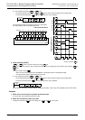
D
1
S
D
1
D
Port No. 1
Port No. 0
Rotary table
X000(M0)
X001(M1)
Detection
switch
0
9
8
7
6
5
4
3
2
1
Command
FNC 68
ROTC
D200 K10 K2 M0
Calling
condition
register
(word device)
Number
of
divisions
Number
of low-
speed
sections
Calling
condition
register
(bit device)
S
D
m1 m2
Product
Zero point
detection
Forward rotation
D
1
S
S
S
S
D
1
D
D
D
D
D
D
D
D
D