


877
FX3G/FX3U/FX3UC Series Programmable Controllers
Programming Manual - Basic & Applied Instruction Edition
38 Error Check Method and Error Code List
38.3 Supplementary Explanation of Devices for Error Detection
31
FNC275-FNC279
Data
Transfer 3
32
FNC280-FNC289
High Speed
Processing 2
33
FNC290-FNC299
Extension File
Register
34
FNC300-FNC305
FX
3U
-CF-ADP
35
SFC•STL
Programming
36
Interrupt
Function
37
Special Device
38
Error Code
A
Version Up
Information
B
Execution Times
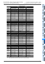
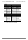
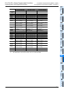
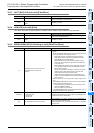
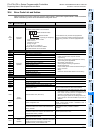
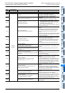
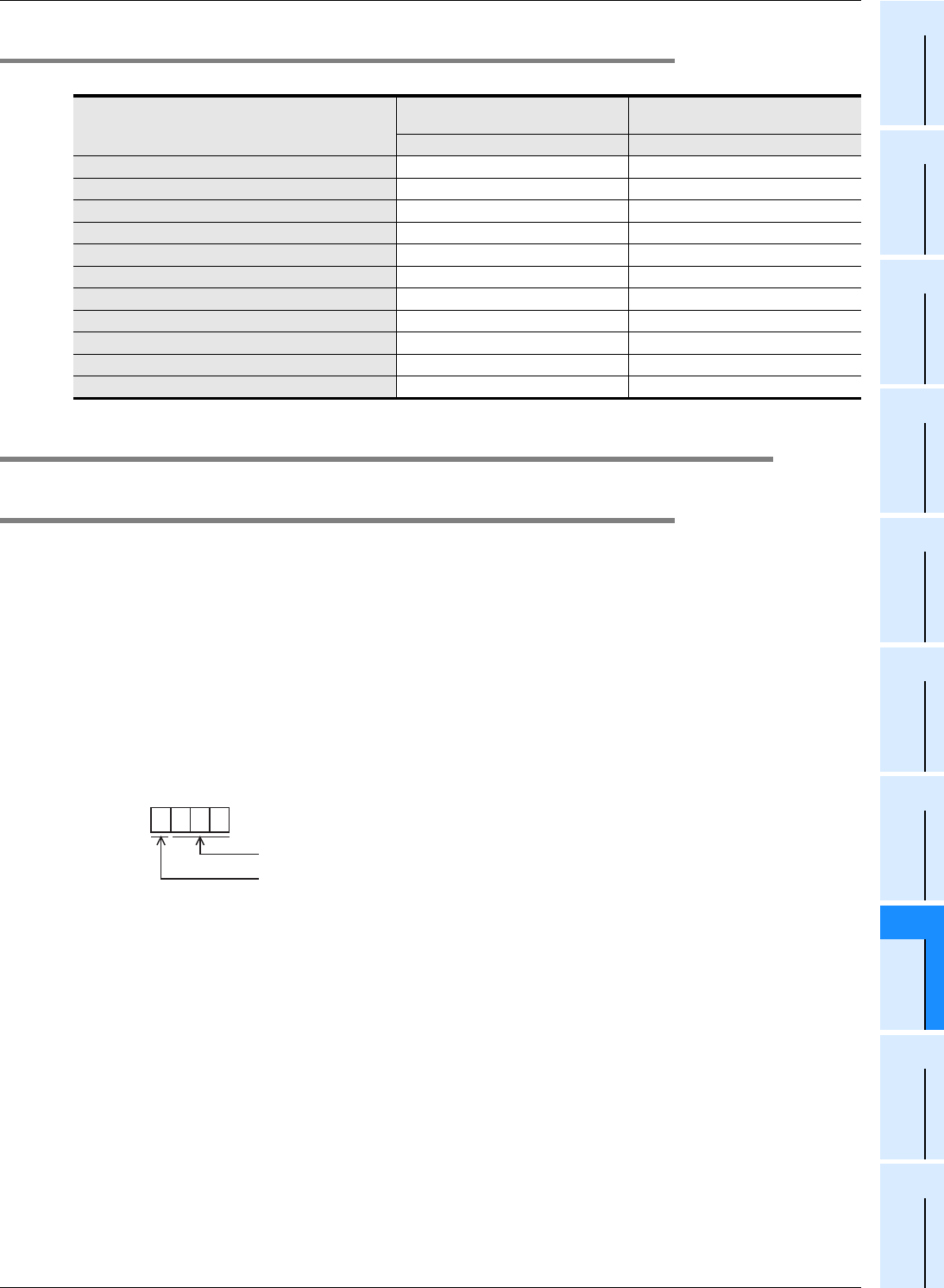
38.2.3 Error indication
The table below shows the error expression in this manual, GX Developer, and display modules (FX3U-7DM).
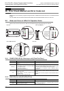
38.3 Supplementary Explanation of Devices for Error Detection
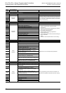
38.3.1 Error detection (M8060 to/D8060 to)
When the M8060, M8061, M8064 to M8067 turn ON, the smallest ON device number is stored in D8004, and M8004
turns ON.
1) M8060,M8061,M8064 to M8067 are cleared when the PLC mode switches from STOP to RUN.
Note that M8068 and D8068 do not clear.
2) When turning M8069 ON in advance, PLC will enter STOP mode (as M8061 PLC hardware error occurs) if a
failure occurs in an I/O extension unit, an extension power supply module, or an extension unit/block.
When turning M8069 ON, PLC executes I/O bus check. If an error is found, error code 6103 or 6104 is stored to
D8061, and M8061 turns ON.
When error code 6104 is stored, M8009 turns ON, and the PLC stores the I/O numbers following the extension
power supply module or the powered extension unit with DC 24V output failure to D8009.
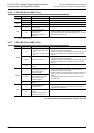
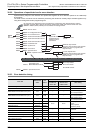
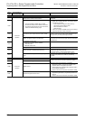
3) If the unit or block corresponding to a programmed I/O number is not actually loaded, M8060 is set to ON and the
first device number of the erroneous block is written to D8060.
*1. 10 to 337 in FX
3U/FX3UC PLCs, and 10 to 177 in FX3G PLCs
4) When a device number is specified directly or indirectly with an index by the LD, AND, OR or OUT instruction, and
if the device numbers specified in those instructions are not actually loaded, M8316 will turn ON and the error step
number in the instruction will be written to D8317 (high-order bits) and D8316 (low-order bits).
This manual
GX Developer
Display modules
FX
3U-7DM
English version Display in English
I/O configuration error I/O config err I/O error
PLC hardware error PLC H/W error PLC H/W error
PLC/PP communication error PLC/PP comm err Comms.error
Serial communication error 1 [ch1] Link error Link error1
Serial communication error 2 [ch2] Link error2 Link error2
Parameter error Param error Parameter error
Syntax error Syntax error Grammar error
Circuit error Ladder error Ladder error
Operation error Operation err Runtime error
BFM initialization failure ––
Special block error – SFB error
1 0 2 0
1: Input (X), 0: Output (Y)
Device number
Example: When X020 is unconnected
BCD conversion value
*1