


751
FX3G/FX3U/FX3UC Series Programmable Controllers
Programming Manual - Basic & Applied Instruction Edition
35 SFC Program and Step Ladder
35.1 SFC Program
31
FNC275-FNC279
Data
Transfer 3
32
FNC280-FNC289
High Speed
Processing 2
33
FNC290-FNC299
Extension File
Register
34
FNC300-FNC305
FX
3U
-CF-ADP
35
SFC•STL
Programming
36
Interrupt
Function
37
Special Device
38
Error Code
A
Version Up
Information
B
Execution Times
35. SFC Program and Step Ladder
This chapter explains the programming procedures and sequence operations for the “SFC” and “step ladder”
programming methods in GX Developer.
35.1 SFC Program
35.1.1 Outline
Sequence control using the SFC (sequential function chart) is available in FX PLCs.
In SFC programs, the role of each process and the overall control flow can be expressed easily based on machine
operations, so sequence design is easy. Accordingly, machine operations can be easily transmitted to any person,
and created programs are efficient in maintenance, specifications changes and actions against problems.
When SFC programs and step ladder instructions are programmed conforming to the same rules, they are compatible
with each other.
As a result, the same contents can be handled in relay ladder charts which are familiar and easy to understand.
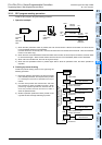
35.1.2 Explanation of function and operation
In SFC programs, a state relay State S is regarded as one control process, and the input conditions and output control
sequence are programmed in each process.
Because the preceding process is stopped when the program execution proceeds to the next process, a machine can
be controlled using simple sequences for each process.
Operation of state relay State S and driven instruction
In SFC programs, each process performed by the machine is expressed by a state relay.
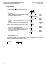
Operations of internal circuits connected to state relays are classified into three types, execution in the contact ON
status, execution in the contact OFF status (for one operation cycle) and non-execution.
• Execution in the contact ON status:
When a state relay turns ON, a connected circuit (internal circuit) is activated with a STL contact.
• Execution in the contact OFF status (for one operation cycle):
When a condition (transfer condition) provided between state relays is satisfied, the next state relay turns ON, and
the state relay which has been ON before hand turns OFF (transfer operation). In the state relay ON status transfer
process, both state relays are ON only momentarily (for one operation cycle). In the next operation cycle after the
ON status is transferred to the next state relay, the former state relay is reset to OFF. A drive instruction connected
to the bus line of the reset state relay is executed in the contact OFF status in one operation cycle regardless of the
actual contact status before the drive instruction. When the transfer state relay S is used in a contact instruction,
however, the contact image is executed in the OFF status immediately after the transfer condition is satisfied.
• Non-execution:
An instruction is not executed in the contact OFF status after the operation cycle where the instruction was
executed in the contact OFF status (jump status).
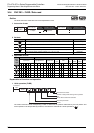
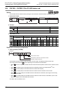
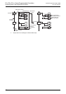
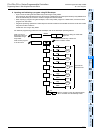
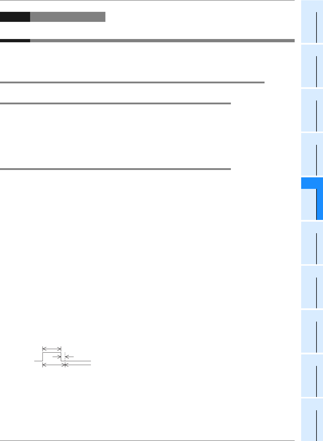
• The figure below shows the timing chart of the state relay (internal circuit) activation status.
• A state relay number can only be used once.
Execution in the contact OFF status
in one operation cycle
Execution in the
contact ON status
Non-execution
(jump status)
Execution