


475
FX3G/FX3U/FX3UC Series Programmable Controllers
Programming Manual - Basic & Applied Instruction Edition
16 External FX Device – FNC 80 to FNC 89
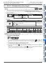
16.9 FNC 88 – PID / PID Control Loop
11
FNC30-FNC39
Rotation and
Shift
12
FNC40-FNC49
Data Operation
13
FNC50-FNC59
High Speed
Processing
14
FMC60-FNC69
Handy
Instruction
15
FNC70-FNC79
External FX I/O
Device
16
FNC80-FNC89
External FX
Device
17
FNC100-FNC109
Data
Transfer 2
18
FNC110-FNC139
Floating Point
19
FNC140-FNC149
Data
Operation 2
20
FNC150-FNC159
Positioning
Control
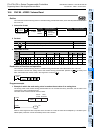
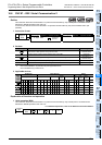
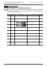
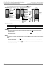
2. Set items
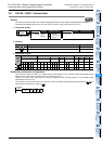
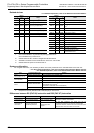
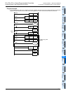
3. List of parameters to +28
Set item Description
Number of
occupied
points
Target value
(SV)
• Set the target value (SV).
• PID instruction does not change the contents of setting.
• Caution on using the auto tuning (limit cycle method)
If the target value for auto tuning is different from the target value for PID control, it is
necessary to set a value including the bias value first, and then store the actual target
value when the auto tuning flag turns OFF.
1
Measured value
(PV)
This is the input value in PID control loop. 1
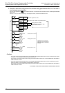
Parameter
*1
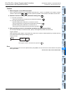
1) Auto tuning: In the case of limit cycle method
Twenty-nine devices are occupied from the head device specified in .
2) Auto tuning: In the case of step response method
a) Operation setting (ACT): When bits 1, 2 and 5 are not all "0"
Twenty-five devices are occupied from the head device specified in .
b) Operation setting (ACT): When bits 1, 2 and 5 are all "0"
Twenty devices are occupied from the head device specified in .
29
25
20
Output value
(MV)
1) In case of PID control (normal processing)
Before driving PID instruction, the user should set the initial output value.
After that, the operation result is stored.
2) Auto tuning: In the case of limit cycle method
During auto tuning, the ULV or LLV value is output automatically.
When auto tuning is finished, the specified MV value is set.
3) Auto tuning: In the case of step response method
Before driving PID instruction, the user should set the initial output value.
During auto tuning, PID instruction does not change the MV output.
1
*1. When auto tuning is not used, the number of points is the same as the number in the step
response method are occupied.
Set item Setting Value Remarks
Sampling time (Ts) 1 to 32767 (ms) It cannot be shorter than the operation cycle.
+1
Operation
setting (ACT)
bit0
0: Forward operation,
1: Backward operation
Operation direction
bit1
0: Input variation alarm is invalid.
1: Input variation alarm is valid.
bit2
0: Output variation alarm is invalid.
1: Output variation alarm is valid.
Do not set to ON bit 2 and bit 5 at the same time.
bit3 Not available
bit4
0: Auto tuning is not executed.
1: Auto tuning is executed.
bit5
0: Upper and lower limits of output
value are not valid.
1: Upper and lower limits of output
value are valid.
Do not set to ON bit 2 and bit 5 at the same time.
bit6
0: Step response method
1: Limit cycle method
Select the auto tuning mode.
bit7 to bit15 Not available
+2
Input filter constant (α) 0 to 99 (%) When "0" is set, the input filter is not provided.
+3
Proportional gain (KP) 1 to 32767 (%)
+4
Integral time (TI) 0 to 32767 (× 100 ms)
When "0" is set, it is handled as "\" (no
integration).
+5
Derivative gain (KD) 0 to 100 (%)
When "0" is set, the derivative gain is not
provided.
+6
Derivative time (TD) 0 to 32767 (× 10 ms)
When "0" is set, the derivative operation is not
executed.
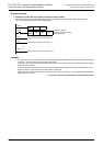
+7
:
+19
These devices are occupied for internal processing in PID control loop. Do not change the data.
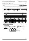
S
1
S
2
S
3
S
3
S
3
S
3
D
S
3
S
3
S
3
S
3
S
3
S
3
S
3
S
3
S
3
S
3
S
3