


650
FX3G/FX3U/FX3UC Series Programmable Controllers
Programming Manual - Basic & Applied Instruction Edition
27 Data Operation 3 – FNC210 to FNC219
27.5 FNC214 – SFL / Bit Shift Left with Carry
27.5 FNC214 – SFL / Bit Shift Left with Carry
Outline
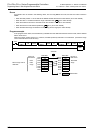
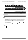
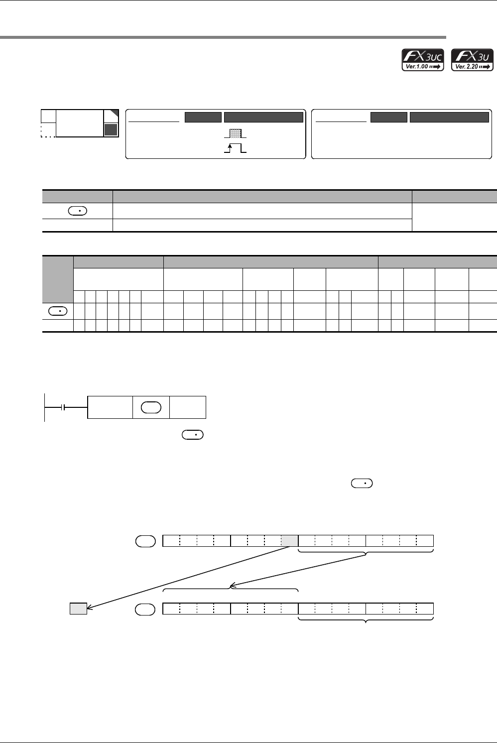
This instruction shifts 16 bits stored in a word device leftward by “n” bits.
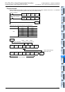
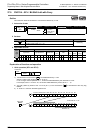
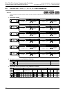
1. Instruction format
2. Set data
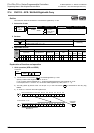
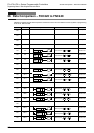
3. Applicable devices
Explanation of function and operation
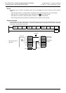
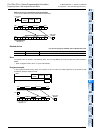
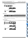
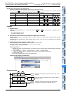
1. 16-bit operation (SFL and SFLP)
1) 16 bits stored in a word device are shifted leftward by “n” bits.
Specify a value in the range from “0” to “15” as “n”.
If “16” or larger value is specified as “n”, 16 bits are shifted leftward by the remainder of “n/16”.
For example, when “n” is set to “18”, 16 bits are shifted leftward by 2 bits (18/16 = 1 ... 2).
2) The ON (1)/OFF (0) status of the “n+1”th bit (bit “n”) in the word device is transferred to the carry flag
M8022.
3) “0” is set to “n” bits from the least significant bit.
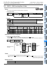
Operand Type Description Data Type
Device number storing data to be shifted
16-bit binary
n Number of times of shift (0 ≤ n ≤ 15)
Oper-
and
Type
Bit Devices Word Devices Others
System User Digit Specification System User
Special
Unit
Index
Con-
stant
Real
Number
Charac-
ter String
Pointer
XYMTCSD
.b KnX KnY KnM KnS T C D R
U\G
V Z Modify K H E "
"P
3333333 3 333
n 33333333 3 33 33
Mnemonic Operation Condition
16-bit Instruction
5 steps
SFL
SFLP
Mnemonic Operation Condition
Continuous
Operation
Pulse (Single)
Operation
32-bit Instruction
⎯
⎯
P
FNC 214
SFL
D
D
FNC214
SFLP
D
n
Command
input
D
D
1
b15
1
b14
1
b13
1
b12
0
b11
0
b10
1
b9
1
b8
0
b7
0
b6
0
b5
0
b4
1
b3
1
b2
1
b1
1
b0
0
b15
0
b14
0
b13
0
b12
1
b11
1
b10
1
b9
1
b8
0
b7
0
b6
0
b5
0
b4
0
b3
0
b2
0
b1
0
b0
1
In the case of “n = 8”
Become “0”.
D
D
Carry flag
M8022