


112
FX3G/FX3U/FX3UC Series Programmable Controllers
Programming Manual - Basic & Applied Instruction Edition
4 Devices in Detail
4.7 High Speed Counter [C] (FX3U/FX3UC PLC)
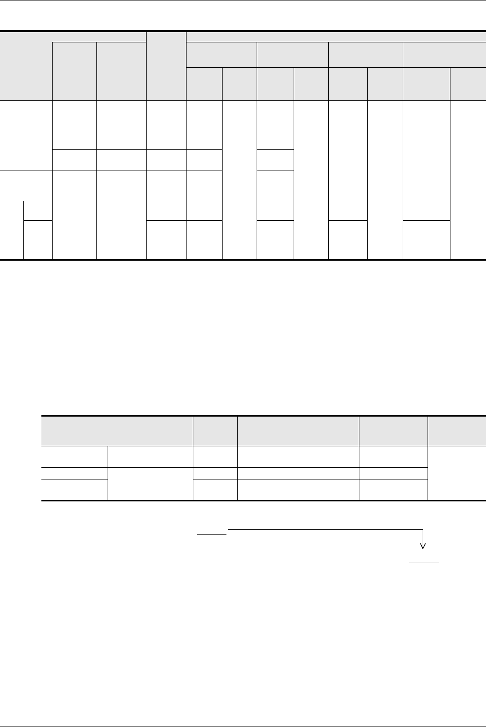
2) When special analog adapters and FX3U/FX3UC Series special function blocks/units are used
*1. When an index register is added to a counter number specified by a HSCS, HSCR, HSZ or HSCT instruction,
all hardware counters are switched to software counters.
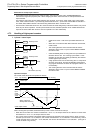
*2. The high speed counters C244 (OP) and C245 (OP) can count up to 10 kHz.
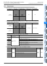
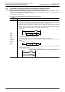
3. Calculation of the total frequency
Total frequency ≥ Sum of "Response frequency of high speed counter ×
Magnification for calculating total frequency"
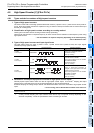
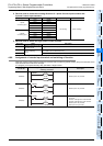
4. Calculation example
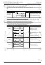
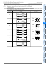
When only HSZ instruction is used 6 times in a program, the total frequency and response frequency are calculated as
follows in accordance with the columns for "When only HSZ instruction is used" shown above.
This calculation example is provided for a system configuration not including special analog adapters and FX
3U/FX3UC
Series special function blocks/units.
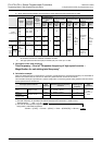
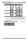
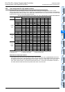
Counter type
Magnifica-
tion for
calculating
total
frequency
Response frequency and total frequency according to instruction use condition
Software
counter
Following
software
counter with
HSCS, HSCR,
HSZ or HSCT
instruction
*1
When HSZ and HSCT
instructions are not
used
When only HSCT
instruction is used
When only HSZ
instruction is used
When both HSZ and HSCT
instructions are used
Maximum
response
frequency
(kHz)
Total
frequency
(kHz)
Maximum
response
frequency
(kHz)
Total
frequency
(kHz)
Maximum
response
frequency
(kHz)
Total
frequency
(kHz)
Maximum
response
frequency
(kHz)
Total
frequency
(kHz)
1-phase
1-counting input
C241,
C242,
C243,
C244,
C245
C235, C236,
C237, C238,
C239, C240
×130
60
25
50
30 - (Num-
ber of
instruc-
tion)
*2
50−
1.5×(Num
ber of
instruc-
tion)
25-(Number
of instruc-
tion)
*2
50−
1.5×(Num
ber of
instruc-
tion)
−
C244(OP),
C245(OP)
×110 10
1-phase
2-counting input
C247,
C248,
C249, C250
C246,
C248(OP)
×130 25
2-
phase
2-
count-
ing
input
1 edge
count
C252,
C253(OP),
C254,
C255
C251, C253
×130 25
4 edge
count
×47.5 6.2
(30-Num-
ber of
instruc-
tion) ÷ 4
(25-Number
of instruc-
tion) ÷ 4
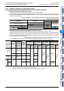
Used high speed counter No.
Input
frequency
Maximum response frequency
calculation
Magnification for
calculating total
frequency
Used
instruction
C237
Operates as
software counter
30 kHz 40 − 6 (times) = 34 kHz × 1
HSZ
instruction × 6
times
C241
Software counter
20 kHz 40 − 6(times) = 34 kHz × 1
C253(OP)
[4 edge count]
4 kHz {40 − 6(times)} ÷ 4 = 8.5 kHz × 4
1) The total frequency is calculated as follows because HSZ instruction is used 6 times:
Total frequency = 80
−
1.5
×
6 = 71 kHz
2) The sum of the response frequencies of the high speed counters
being used is calculated as follows:
"30 kHz
×
1[C237]" + "20 kHz
×
1[C241]" + "4kHz
×
4[C253(OP)]" = 66 kHz
≤
71 kHz