


201
FX3G/FX3U/FX3UC Series Programmable Controllers
Programming Manual - Basic & Applied Instruction Edition
7 Basic Instruction
7.9 MC, MCR
1
Introduction
2
Overview
3
Instruction
List
4
Devices
in Detail
5
Specified the
Device &
Constant
6
Before
Programming
7
Basic
Instruction
8
FNC00-FNC09
Program Flow
9
FNC10-FNC19
Move & Compare
10
FNC20-FNC29
Arith. & Logic
Operation
7.9 MC, MCR
Outline
When MC instruction is executed, the bus line (LD or LDI point) is moved to a position after MC contact.
The bus line can be returned to the original position by MCR instruction.
By changing a device (Y or M) number, MC instruction can be used as many times as necessary.
If a same device number is used twice, however, it results in the double coil operation in the same way as OUT
instruction.
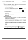
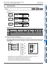
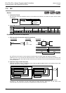
1. Instruction format
→ For the number of steps of MC instruction, refer to Section 7.15.
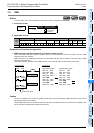
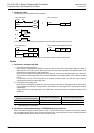
2. Applicable devices
S: Except special auxiliary relays (M)
Explanation of function and operation
1. MC and MCR instructions (denotes the start of a master control block and denotes the end of a
master control block)
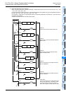
When MC instruction is executed, the bus line is moved to a position after MC contact.
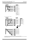
Drive instructions connected to the bus line after the MC contact execute each operation only when the MC instruction
is executed, and execute each operation in the contact OFF status without regard to the contact status before drive
instructions when a MC instruction is not executed. If an instruction (such as FOR/NEXT, EI and DI instruction) not
requiring a contact instruction exists in a circuit using master control, such an instruction is executed without regard to
the MC instruction execution command.
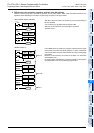
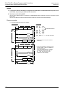
In the program example below, the instructions from MC to MCR are executed as they are while the input X000 is ON.
However, while the input X000 is OFF, each driven device offers the following operation:
Timers (except retentive type timers) and devices driven by OUT instruction: Turn OFF.
Retentive type timers, counters and devices driven by SET/RST instruction: Hold the current status.
The expressions of circuit programs used to explain operations are circuits (for reading or monitoring) of GX
Developer.
Instruc-
tion
Bit Devices Word Devices Others
System User Digit Specification System User
Special
Unit
Index
Con-
stant
Real
Number
Charac-
ter String
Pointer
XYMTCSD.b KnX KnY KnM KnS T C D R U\G VZModifyKH E ""P
MC 3 S
MCR There are no applicable devices.
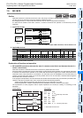
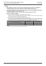
MC
Master Control
Basic Instruction
MC
−
Continuous
Operation
Pulse (Single)
Operation
Mnemonic Operation Condition
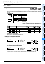
MCR
Master Control
Reset
Basic Instruction
2 steps
MCR
−
Continuous
Operation
Pulse (Single)
Operation
Mnemonic Operation Condition
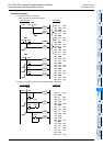
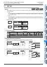
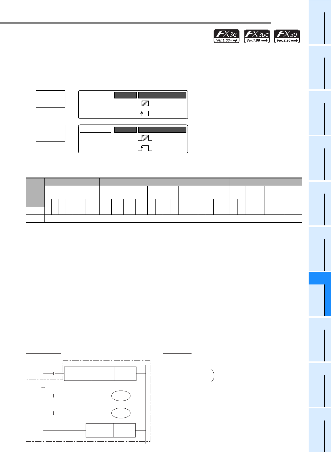
Circuit program List program
X000
MC N 0 M100
N 0 M100
X001
Y000
X002
Y001
MCR N 0
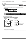
0000 LD X000
0001 MC N000
SP M100
0004 LD X001
0005 OUT Y000
0006 LD X002
0007 OUT Y001
0008 MCR N 0 ← Two-step instruction
Three-step instruction
← Write MCR N0 instruction.