


803
FX3G/FX3U/FX3UC Series Programmable Controllers
Programming Manual - Basic & Applied Instruction Edition
36 Interrupt Function and Pulse Catch Function
36.3 Input Interrupt (Interrupt Triggered by External Signal) [Without Delay Function]
31
FNC275-FNC279
Data
Transfer 3
32
FNC280-FNC289
High Speed
Processing 2
33
FNC290-FNC299
Extension File
Register
34
FNC300-FNC305
FX
3U
-CF-ADP
35
SFC•STL
Programming
36
Interrupt
Function
37
Special Device
38
Error Code
A
Version Up
Information
B
Execution Times
5. How to disable each interrupt input
When either one among M8050 to M8055 is set to ON in a program, interrupts from the corresponding input number
are disabled.
(Refer to the above table for the correspondence.)
6. Cautions
1) Do not use an input two or more times
Make sure that an input relay number used as an interrupt pointer is not used in high speed counters, pulse catch
functions and applied instructions such as FNC 56 (speed detection) which use the same input range.
2) Automatic adjustment of the input filter
When an input interrupt pointer I0 is specified, the input filter of the input relay is automatically changed to the
input filter for high speed receiving.
Accordingly, it is not necessary to change the filter value using REFF (FNC 51) instruction or special data register
D8020 (input filter adjustment).
The input filter of an input relay not being used as an input interrupt pointer operates at 10 ms (initial value).
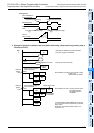
3) Pulse width of input interrupt
For executing input interrupt by an external signal, it is necessary to input the ON or OFF signal having the
duration shown in the table below or more.
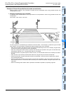
*1. When using the input filter at the filter value of 5 µs or when receiving a pulse whose response frequency is
50 k to 100 kHz using a high speed counter, perform the following:
- Make sure that the wiring length is 5 m or less.
- Connect a bleeder resistor of 1.5 kΩ (1 W or more) to an input terminal, and make sure that the load
current of the open collector transistor output in the counterpart equipment is 20 mA or more including the
input current in the main unit.
4) Using a pointer number two or more times
It is not possible to program an interrupt at the rising edge and an interrupt at the falling edge for an input such as
I001 or I000.
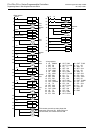
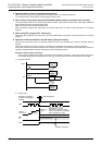
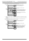
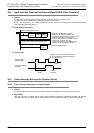
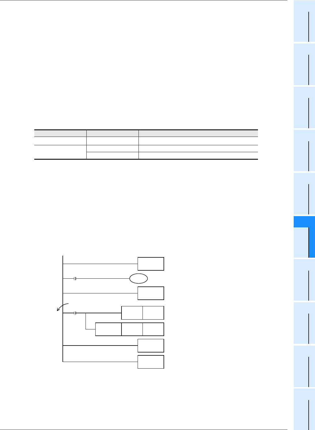
7. Program examples
1) When using both an external input interrupt at the rising edge and the output refresh (REF instruction)
In the program example shown below, the output Y000 immediately turns ON when the rising edge of the external
input X000 is detected.
*1. Make sure to specify a multiple of "8" for the number of inputs/outputs to be refreshed by REF (FNC 50)
instruction.
If any value other than a multiple of "8" is specified, an operation error occurs and REF (FNC 50) instruction is
not executed.
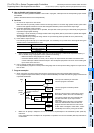
PLC Input number Input filter value when "0" is set
FX
3U, FX3UC X000 to X005
5µs
*1
FX3G
X000,X001,X003,X004 10µs
X002,X005 50µs
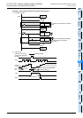
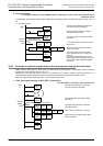
Step
0
I001
Interrupt
pointer
When the rising edge
of X000 is detected
M8000
RUN
monitor
FNC 06
FEND
FNC 04
EI
Y000 K8
*1
FNC 50
REF
FNC 03
IRET
END
SET Y000
Interrupts are enabled by EI instruction.
The main program is described.
The main program is finished by FEND
instruction.
When an interrupt routine is executed by turning
ON of X000, Y000 is set to ON unconditionally.
The outputs Y000 to Y007 are overwritten with
the latest information by the output refresh
instruction.
If the output refresh instruction is not provided,
Y000 turns ON after END instruction after the
program execution returned to the main routine.
If "SET Y000" is changed to "RST Y000", Y000 is
immediately set to OFF by turning ON of X000.