


734
FX3G/FX3U/FX3UC Series Programmable Controllers
Programming Manual - Basic & Applied Instruction Edition
33 Extension File Register Control – FNC290 to FNC299
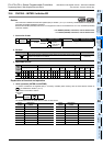
33.6 FNC295 – INITER / Initialize ER
Operation
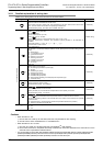
• Extension file registers (ER) [inside the memory cassette]
Caution
About 25 ms is required to initialize one sector.
When initializing two or more sectors, take either measure shown below.
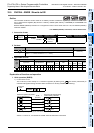
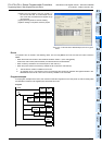
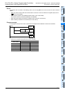
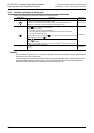
• Set a large value to the watchdog timer D8000 using the following program
Guideline of the watchdog timer set value
A value acquired by the following procedure can be regarded as the guideline of the watchdog timer set value.
If an acquired value is 200 ms or less, however, it is not necessary to change the watchdog timer set value.
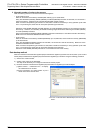
1) Write a program to be executed from GX Developer to the PLC.
[Online]→[Write to PLC...]
2) Set the current value of D8000 (unit: ms) to "1000" using the device test function in GX Developer.
[Online]→[Debug]→[Device test...]→ "Word device/buffer memory" in Device test dialogbox
3) Set the PLC mode to RUN, and execute the program. (Execute this instruction also.)
4) Monitor the maximum scan time D8012 (unit: 0.1ms) using the device batch monitoring function in GX Developer.
5) Set the watchdog timer to the maximum scan time (D8012) or more.
D8012 stores the maximum scan time in increments of 0.1 ms.
Rough guide to the watchdog timer set value D8000 (unit: ms) is the "value stored in D8012 divided by 10" added
by 50 to 100.
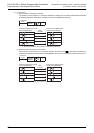
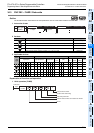
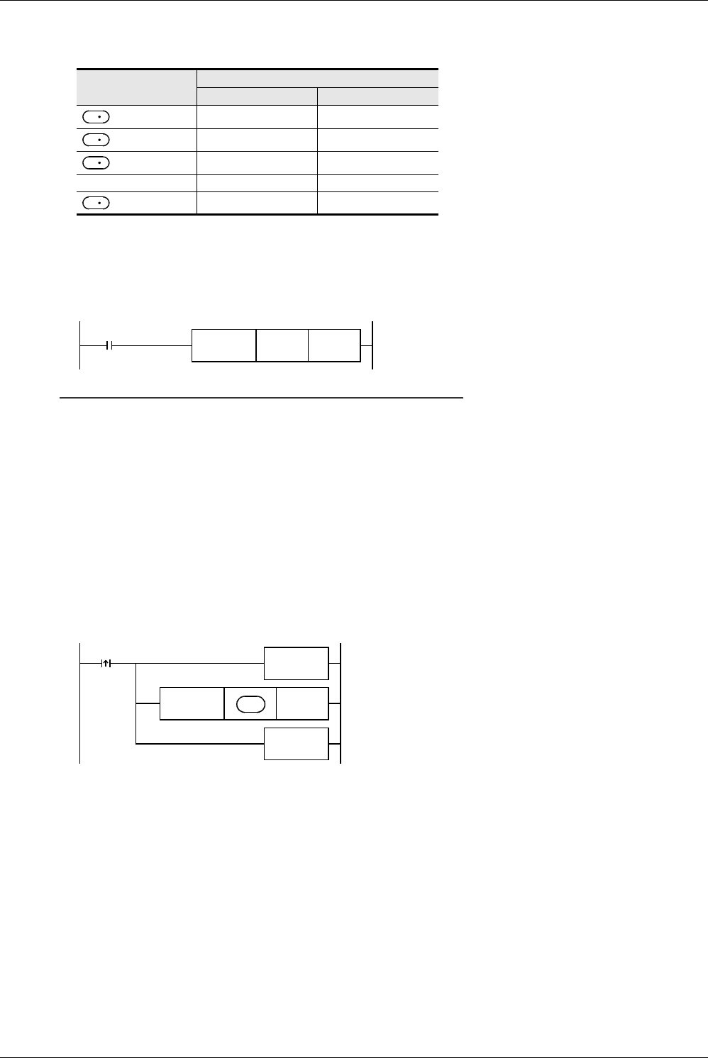
• Setting WDT (FNC 07) instruction just before and after INITER instruction as shown below:
If the processing time of the INITER command exceeds 200ms, set the watchdog timer value D8000 (unit: ms) to the
processing time or more.
2. Allowable number of writes to the memory
Note the following cautions on access to extension file registers.
• Data can be written to the memory cassette (flash memory) up to 10,000 times.
Every time the INITR (FNC292), RWER (FNC294) or INITER (FNC295) instruction is executed, it is counted as a
write to the memory. Make sure not to exceed the allowable number of writes.
When a continuous operation type instruction is used, data is written to the memory in every operation cycle of the
PLC. For preventing this, make sure to use a pulse operation type instruction.
• Execution of the LOADR (FNC290), SAVER (FNC291) or LOGR (FNC293) instruction is not counted as a write to
the memory. However, it is necessary to initialize the writing target sector before executing the SAVER (FNC291)
or LOGR (FNC293) instruction.
Every time the INITR (FNC292)or INITER (FNC295) instruction is executed, it is counted as a write to the memory.
Make sure not to exceed the allowable number of writes.
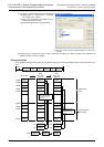
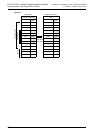
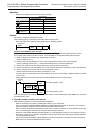
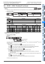
Device number
Current value
Before execution After execution
H1234 HFFFF
+1
H5678 HFFFF
+2
H90AB HFFFF
...
...
...
+(2048×n)-1
HCDEF HFFFF
S
S
S
S
M8002
FNC 12
MOV
K
{{{
D8000
Initial pulse
The watchdog timer is reset.
FNC295
INITER
n
FNC 07
WDT
FNC 07
WDT
The watchdog timer is reset.
Command
input
S