465
FX3G/FX3U/FX3UC Series Programmable Controllers
Programming Manual - Basic & Applied Instruction Edition
16 External FX Device – FNC 80 to FNC 89
16.5 FNC 84 – CCD / Check Code
11
FNC30-FNC39
Rotation and
Shift
12
FNC40-FNC49
Data Operation
13
FNC50-FNC59
High Speed
Processing
14
FMC60-FNC69
Handy
Instruction
15
FNC70-FNC79
External FX I/O
Device
16
FNC80-FNC89
External FX
Device
17
FNC100-FNC109
Data
Transfer 2
18
FNC110-FNC139
Floating Point
19
FNC140-FNC149
Data
Operation 2
20
FNC150-FNC159
Positioning
Control
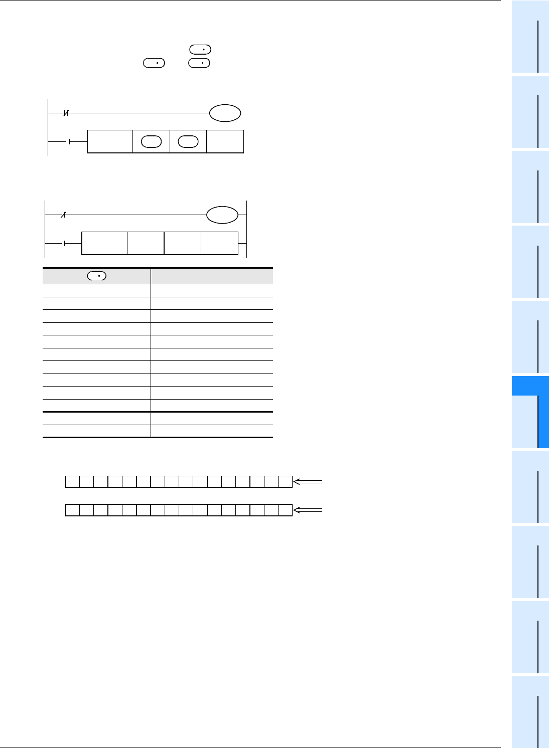
2. 16-bit conversion mode (while M8161 is OFF)
(M8161 is also used for the RS, ASCI, HEX and CRC instructions.)
With regard to "n" data starting from , the addition data and horizontal parity data of high-order 8 bits and low-
order 8 bits are stored to and +1 respectively.
M8161 is used also for the RS, ASCI, HEX and CRC instructions. When using the 16-bit mode, set M8161 to normally
OFF. M8161 is cleared when the PLC mode is changed from RUN to STOP.
Example of 16-bit conversion
In the following program, conversion is executed as follows:
Example of data contents
Low-order 8 bits of D100 K100 = 01100100
High-order 8 bits of D100 K111 = 0110111 (1) ←
Low-order 8 bits of D101 K100 = 01100100
High-order 8 bits of D101 K 98 = 01100010
Low-order 8 bits of D102 K123 = 0111101 (1) ←
High-order 8 bits of D102 K 66 = 01000010
Low-order 8 bits of D103 K100 = 01100100
High-order 8 bits of D103 K 95 = 0101111 (1) ←
Low-order 8 bits of D104 K210 = 11010010
High-order 8 bits of D104 K 88 = 01011000
Total K1091
Horizontal parity 1000010 (1)
← When the number of "1" is odd, the horizontal parity is "1".
When the number of "1" is even, the horizontal parity is "0".
S
D
D
M8161
M8000
FNC 84
CCD
nS
Command
input
D
16-bit mode
M8161
M8000
FNC 84
CCD
D100 D0 K10
X010
16-bit mode
S
1100001000100000
D 0
"1091" in BCD
1010000100000000
D 1
Horizontal parity


