


432
FX3G/FX3U/FX3UC Series Programmable Controllers
Programming Manual - Basic & Applied Instruction Edition
15 External FX I/O Device – FNC 70 to FNC 79
15.5 FNC 74 – SEGL / Seven Segment With Latch
15.5 FNC 74 – SEGL / Seven Segment With Latch
Outline
This instruction controls one or two sets of 4-digit seven-segment display units having the latch function.
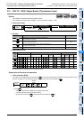
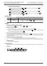
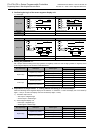
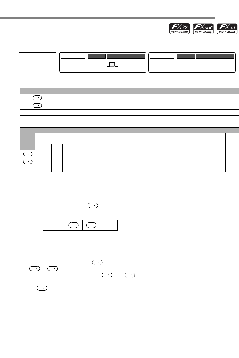
1. Instruction format
2. Set data
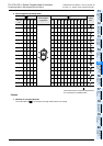
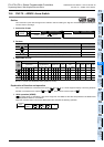
3. Applicable devices
S: This function is supported only in FX3U/FX3UC PLCs.
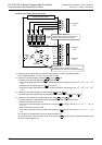
Explanation of function and operation
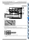
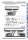
1. 16-bit operation (SEGL)
The 4-digit numeric value stored in is converted into BCD data, and each digit is output to the seven-segment
display unit with the BCD decoder in the time division method.
When using one set of 4 digits (n = K0 to K3)
→ For selection of "n", refer to Subsection 15.5.2.
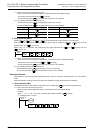
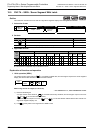
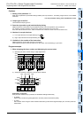
1) Data and strobe signal
A 4-digit numeric value stored in is converted from binary into BCD, and each digit is output in turn from
to +3 in the time division method.
The strobe signal is output in turn from +4 to +7 in the time division method also to latch one set of 4-
digit seven-segment display unit.
2) For , binary data in the range from 0 to 9999 is valid.
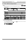
Operand Type Description Data Type
Head word device converted into the BCD format 16-bit binary
Head Y number to be output Bit
n Parameter number [setting range: K0 (H0) to K7 (H7)] 16-bit binary
Oper-
and
Type
Bit Devices Word Devices Others
System User Digit Specification System User
Special
Unit
Index
Con-
stant
Real
Number
Charac-
ter String
Pointer
XYMTCSD
.b KnX KnY KnM KnS T C D R
U\G
V Z Modify K H E "
"P
33333333 S 33 3 33
3 3
n 33
−
32-bit Instruction
Mnemonic Operation Condition
FNC 74
SEGL
SEGL
16-bit Instruction
7 steps
Mnemonic Operation Condition
Continuous
Operation
S
D
S
D
S
Command
input
FNC 74
SEGL
nS
D
S
D
D
D
D
S